Что такое ардуино и для чего нужен?
Содержание:
- Установка Python
- Замедление тактовой частоты Arduino
- Step 3: Switch and LED and Using Pin Bank D.
- Вступление
- Функция pinMode()
- Скетч
- Step 2: Blink an LED
- Замена или пренебрежение энергопотреблением компонентов
- Analog Write with 12 LEDs on an Arduino Mega
- Analog Input
- Скетч Ардуино
- Устройство и принцип работы потенциометра
- Robot library
- Заключение
Установка Python
Сначала, вам нужно будет скачать python на свой компьютер, чтобы продолжить работу с платой.
Выполните следующие шаги, которые я привел ниже.
Упомянутые ниже шаги применимы только для пользователей Windows, работающих на 32-битной или 64-битной ОС. Процедура установки для MAC и Linux отличается.
Нам нужно скачать среду с официального сайта «Питона» отсюда.
Нажмите на 32-битный Python-2.7.9, что установит 32-битный Python IDLE на ваш компьютер.
Важно! Не загружайте 64-битную версию или обновленные версии, поскольку они не обеспечивают поддержку наших библиотек Arduino. Даже если ваш компьютер работает на 64-битной версии, вы можете использовать 32-битный Python.
Откройте загруженный exe-файл и следуйте инструкциям
Не меняйте каталог, в который устанавливается «питон». Это будет: C:\Python27 по умолчанию, оставьте это таковым.
Во время установки вы можете получить предупреждение от вашего антивируса (если он есть), в этом случае нажмите «Разрешить».
Замедление тактовой частоты Arduino
Тактовая частота платы Arduino определяет, сколько операций она может выполнять в секунду. Большинство плат Arduino работают с тактовой частотой 16 МГц. Уменьшение этого значения до 8 МГц может снизить необходимый ток с 12 мА до 8,5 мА. В долгосрочной перспективе метод может отключить большую часть энергопотребления и продлить срок службы батареи.
Поэтому, если вам не нужно выполнять большое количество инструкций за короткое время, важно уменьшить тактовую частоту, если вы хотите сэкономить электроэнергию и выполнить некоторые операции. Однако этот метод не очень удобен в большинстве случаев, и если вы можете поместить свою плату в глубокий сон, то этот метод гораздо менее эффективен
Важно! Изменение тактовой частоты может привести к проблемам с загрузчиком и повреждению Arduino.
Пример кода замедления частоты
#include <avr/power.h>

void setup() {
  if(F_CPU == 8000000) clock_prescale_set(clock_div_2);
  if(F_CPU == 4000000) clock_prescale_set(clock_div_4);
  if(F_CPU == 2000000) clock_prescale_set(clock_div_8);
  if(F_CPU == 1000000) clock_prescale_set(clock_div_16);
}
Step 3: Switch and LED and Using Pin Bank D.
Bank D controls pins 0 — 7, but pins 0 and 1 are used for serial communication. Most Arduino enthusiasts do not try to use these pins for anything else. Things can get weird if you mess with these pins. So for safety it is best to preserve the values of bits 0 and 1 in the DDRD and PORTD registers. This requires the use of logical AND and OR commands.
Each register is 8 bits numbered 0 to 7 from right to left. Bit 0 is 2^0, bit 1 is 2^1, etc.
A logical OR compares two bytes bit for bit and the result is 1 if either or the bytes is 1, if not the result is 0.
The vertical line (|) is the symbol for a logical OR.
Here is a truth table for a logical OR:
0 | 0 = 0
0 | 1 = 1
1 | 0 = 1
1 | 1 = 1
So if we OR        11001100
Against            00111100
The result will be 11111100
A logical AND compares two bytes bit for bit and the result is 1 only if both bits are 1.The ampersand (&) is the symbol for a logical AND.
Here is a truth table for a logical AND:
0 & 0 = 0
0 & 1 = 0
1 & 0 = 0
1 & 1 = 1
So if we AND       11001100
Against            00111100
The result will be 00001100
In order to preserve a bit you can OR it against 0 or AND it against 1.
Follow along with the documentation in the program to see how this works.
Build the circuit shown in the diagram, you will need:
- Arduino
- Breadboard
- LED
- Resistor, 330-560 Ohm
- Jumper wires
Copy this program into the Arduino IDE and upload it to your Arduino:
/*********************************************************
 * Demonstration using bank D pins 0 - 7 and preserving the
 * values of pins 0 and 1 in the DDRD and PORTD registers.
 *
 * The anode of an LED is connected to pin 7 with
 * a resistor in series connected to ground.
 *
 * A pushbutton switch is connected to pin 2 and ground
 * and uses the internal pull-up resistor.
 *
 * The LED lights when the button is pressed.
 *
 *********************************************************/

/**********************************************
 * setup() function
 **********************************************/
void setup()
{
  // Set pin 2 to input and pin 7 to output
  // while maintaining the state of pins 0 and 1.
  // We don't care what happens to 3 - 6.

  DDRD = DDRD | B10000000;

  // The "|" means a logical OR.
  // We now know that bit 7 is high.
  // And we know bits 0 and 1 are preserved.
  // But we still are not sure of bit two.

  DDRD = DDRD & B10000011;

  // We do a logical AND, now we know the status of all the bits.

  // A logical OR against zero or a logical AND against one
  // will not change the status of a bit.

  // This preserved the status of bits 7, 1, and 0.
  // Since bit 2 was ANDed against 0 we know that it is now clear.
  // The DDRD register is now where we want it.

  // Now we need to get the PORTD register set the way we want it.

  PORTD = PORTD & B00000011;

  // Bits 0 and 1 are preserved, all others are off.

  PORTD = PORTD | B00000100;

  // Bits 7 is off, the initial state of the LED.
  // Bit 2 is on, because pin 2 is an input turning it's bit
  // on in PORTD turns on the internal pull-up resistor.
}

/**********************************************
 * loop() function
 **********************************************/
void loop()
{
  // Read the PIND register.

  int button = PIND;

  // you now have the values of all eight pins in the PIND register
  // contained in a variable. The only pin we care about is pin 2.
  // So we do a logical AND on the button variable to isolate the
  // bit we want.

  button = button & B00000100;

  // Because of the internal pull-up resistor the pin will be high
  // if the button is not pressed, and low if it is.
  // So button will return either 2^2 (4) or zero if it is pressed.

  PORTD = PORTD & B00000111;

  // Turn LED off, and preserve bits 0 - 2.

  if(button == 0)
  {
    PORTD = PORTD | B10000000;
  // turn LED on, and preserve bits 0 - 2.
  }
}
The digitalWrite() command will slow a program down a lot in a loop, but the pinMode() command is normally used only in the setup() function and run once. the program above will run just as well if you use a more standard setup() function, like this:
setup()
{
  pinMode(7, OUTPUT);
  pinMode(2, INPUT_PULLUP;
}
While using the DDRD register is not necessary it is nice to understand how it and the logical operations work.
Вступление
Arduino Uno и Pro Mini не работают эффективно в ситуациях, когда с ними приходится работать с использованием батареек. В таких ситуациях каждый миллиампер тока имеет значение. Arduino Uno потребляет минимум 15 мА тока, что звучит не так плохо, но в определенных ситуациях эта цифра быстро возрастает.
Arduino Uno — это плата, построенная с несколькими различными схемами, включая USB-последовательный преобразователь, регуляторы, индикаторы, процессоры, цепь защиты от короткого замыкания, цепи управления повреждением и т.д. Она потребляет больше энергии, чем необходимо.
Далее мы рассмотрим различные способы снижения энергопотребления Arduino путем изменения аппаратного обеспечения или использования программного кода.
Функция pinMode()
Но пойдем по порядку. Мы уже знаем из Урока 6 две основные функции void setup() и void loop(). Далее мы будем работать в них.
Для нашего урока нам нужна новая функция о которой мы пока не проходили — pinMode(). Эта функция сообщает Arduino выводить напряжение или измерять напряжение на цифровом выводе. Мы будем использовать эту новую функцию именно в void setup(), т.к. наша новая функция относится к настройкам.
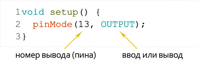
Функция pinMode() принимает два аргумента. Аргументы — это информация, необходимая функции для выполнения своей задачи. Они помещаются в скобки функции и разделяются запятой.
- Первый аргумент функции pinMode() — это номер пина, т.е. 13 в нашем примере (см. схему выше).
- Второй аргумент устанавливает режим ввода или вывода. В примере выше — вывод.
Используйте OUTPUT, если вы хотите вывести напряжение, и используйте INPUT, если вы хотите прочитать напряжение.
Мы собирались использовать режим OUTPUT, так как мы хотим отправить ток на светодиод.
Скетч
После подготовки и сборки компонентов, мы готовы программировать наши платы. Для этого проекта обе платы будут иметь одинаковые скетчи.
Сначала, мы устанавливаем режим контакта 8 (кнопка) в , режим контакта 13 (светодиод) в и устанавливаем начальное состояние контакта 13 в состояние (светодиод выключен).
Как всегда, Arduino позволяет нам легко использовать встроенное оборудование UART с помощью объекта serial. Последовательный serial объект имеет необходимые функции для простого использования UART-интерфейса Arduino.
Serial.begin()
Для связи через UART-интерфейс необходимо сначала его настроить. Самый простой способ настроить UART Arduino — это использовать функцию . Параметр («Скорость») — это скорость передачи данных, с которой мы хотим запустить UART. С помощью этой функции остальные параметры UART будут установлены на значения по умолчанию:
- Data length = 8 (длина данных)
- Parity bit = 1 (бит четности)
- Number of Stop Bits = None (количество стоп-битов = нет)
Если настройки по умолчанию для вас не работают, используйте функцию вместо . Дополнительный параметров используется для изменения настроек длины блока данных, бита четности, количества стоповых битов. Определенные значения для конфигурирования параметра можно найти здесь.
Нижеприведенный код добавляет внутри для инициализации Arduino Uno UART со скоростью 9600 бит/с и другими параметрами, установленными по умолчанию.
Следующая часть кода — это чтение и сохранение значения, полученного из последовательного интерфейса. Для этого мы будем использовать функцию вместе с оператором , чтобы проверить, не получены ли данные. Затем мы вызовем для получения одного байта полученных данных и сохраним значение в переменную . Значение управляет включением/выключением встроенного светодиода.
Serial.available()
Для проверки наличия данных, ожидающих чтения в буфере UART (или в последовательном интерфейсе), воспользуемся функцией . возвращает количество байт, ожидающих чтения в буфере.
Serial.read()
Для чтения данных, ожидающих в последовательном буфере, будем использовать функцию . Эта функция возвращает один байт данных, считанных из буфера.
Serial.write()
Для отправки данных через контакты Arduino TX0 мы будем использовать функцию . Параметр — это байт (или серия байтов), который будет отправлен.
В нашем скетче мы будем посылать значение в зависимости от состояния контакта 8. Мы отправим значение char ‘1’, если пин 8 HIGH, или значение char ‘0’, если пин 8 LOW.
Step 2: Blink an LED
For these first programs all that is needed is a working Arduino, we will be blinking the internal LED on digital pin 13. Copy these programs into the Arduino IDE and upload them to your Arduino.
Here is the first program:
/********************************************************
 * setup() function
 *
 * Set B5 (Digital pin 13) to output by changing the DDRB
 * register instead of using pinMode().
 *******************************************************/
void setup()
{
  DDRB = B00100000;
}

/****************************************************************
 * loop() function
 *
 * Turn the LED attached to B5 (Digital pin 13) on and off
 * by changing the PORTB register instead of using digitalWrite().
 ****************************************************************/
void loop()
{
  PORTB = B00100000; //Turn LED on.
  delay(1000);
  PORTB = B00000000; //Turn LED off.
  delay(1000);
}
The «B» before the number tells the compiler to interpret the number as binary.
The bits are numbered 0 to 7, the right most bit is the zero bit (2^0).
It will also work with decimal numbers, use whatever is most convenient.
Here is an example with decimal numbers:
void setup()
{
  DDRB = 32;
}

void loop()
{
  PORTB = 32; //Turn LED on.
  delay(1000);
  PORTB = 0; //Turn LED off.
  delay(1000);
}
It will even work if the values are in variables, binary or decimal:
int on = B00100000;
int off = B00000000;

void setup()
{
  DDRB = on;
}

void loop()
{
  PORTB = on; //Turn LED on.
  delay(1000);
  PORTB = off; //Turn LED off.
  delay(1000);
}
As mentioned in step 1 bits six and seven are mapped to the crystal, just leave them alone and you will be all right.
Замена или пренебрежение энергопотреблением компонентов
Встроенный регулятор напряжения ограничивает входное напряжение входного разъема постоянного тока. Регулятор не очень эффективен и около 58% входной энергии теряется в виде тепла или используется для внутреннего питания. Лучше заменить этот компонент более эффективными понижающими преобразователями постоянного тока DC-DC. Некоторые ступенчатые преобразователи постоянного тока или понижающие преобразователи могут достигать 92%.
Arduino Uno использует небольшой линейный регулятор напряжения в TO223 SMD пакете. Чипсет Traco TSRN1 — отличный вариант для пакета, доступного на Arduino Uno.
Питание 5V регулируемого напряжения через 7805 IC извне является гораздо более эффективным способом. Это лучший вариант для удаления встроенного регулятора для снижения энергопотребления. Без регулятора напряжения сбрасывается ток около 2,7 мА.
Индикатор питания (светодиод) постоянно горит, что указывает на то, что плата получает достаточное количество питания. Снятие светодиода питания может снизить ток в 2,85 мА в нормальном режиме. В спящем режиме без светодиода энергопотребление Arduino UNO составляет всего 30,8 мкА.
Analog Write with 12 LEDs on an Arduino Mega
This example fades 12 LEDs up and the down, one by one, on an Arduino or Genuino Mega board, taking advantage of the increased number of PWM enabled digital pins of this board.
Circuit
Connect the longer, positive legs (anodes) of 12 LEDs to digital pins 2-13 through 220 ohm current limiting resistors. Connect the shorter, negative legs (cathodes) to ground.
Code
In the function of the code below, a loop is used to assign digital pins 2-13 of the Mega as outputs.
Next, in the function of the program below, a trio of nested loops are used.
The first of these loops,
moves through each of the LEDS one by one, from the lowest pin to the highest. Before this loop is allowed to move from one pin to the next, two things must be accomplished. First, you brighten the individual LED through these lines of code:
With each pass through the loop above, the variable brightness increases by one point, and that value is written to the pin currently selected to the main loop. One that pin reaches the maximum PWM value (255), the following loop kicks in:
This loop subtracts a point from the brightness variable, dimming the LED back down to 0. Once zero is reached, the main loop kicks in, and the program moves on to the next LED pin, repeating all the steps mentioned above.
/*
Mega analogWrite() test
This sketch fades LEDs up and down one at a time on digital pins 2 through 13.
This sketch was written for the Arduino Mega, and will not work on other boards.
The circuit:
— LEDs attached from pins 2 through 13 to ground.
created 8 Feb 2009
by Tom Igoe
This example code is in the public domain.
http://www.arduino.cc/en/Tutorial/AnalogWriteMega
*/// These constants won’t change. They’re used to give names to the pins used:
const int lowestPin = 2;
const int highestPin = 13;void setup() {
// set pins 2 through 13 as outputs:
for (int thisPin = lowestPin; thisPin <= highestPin; thisPin++) {
pinMode(thisPin, OUTPUT);
}}void loop() {
// iterate over the pins:
for (int thisPin = lowestPin; thisPin <= highestPin; thisPin++) {
// fade the LED on thisPin from off to brightest:
for (int brightness = ; brightness < 255; brightness++) {
analogWrite(thisPin, brightness);
delay(2);
}
// fade the LED on thisPin from brightest to off:
for (int brightness = 255; brightness >= ; brightness—) {
analogWrite(thisPin, brightness);
delay(2);
}
// pause between LEDs:
delay(100);
}}
See Also:
- for()
- analogWrite()
-
delay()
- AnalogInOutSerial — Read an analog input pin, map the result, and then use that data to dim or brighten an LED.
- AnalogInput — Use a potentiometer to control the blinking of an LED.
- Calibration — Define a maximum and minimum for expected analog sensor values.
- Fading — Use an analog output (PWM pin) to fade an LED.
- Smoothing — Smooth multiple readings of an analog input.
Last revision 2015/07/28 by SM
Analog Input
In this example we use a variable resistor (a potentiometer or a photoresistor), we read its value using one analog input of an Arduino or Genuino board and we change the blink rate of the built-in LED accordingly. The resistor’s analog value is read as a voltage because this is how the analog inputs work.
Hardware Required
- Arduino or Genuino Board
- Potentiometer or
- 10K ohm photoresistor and 10K ohm resistor
- built-in LED on pin 13 or
- 220 ohm resistor and red LED
Circuit
With a potentiometer
click the image to enlarge
With a photoresistor
click the image to enlarge
Connect three wires to the Arduino or Genuino board. The first goes to ground from one of the outer pins of the potentiometer. The second goes from 5 volts to the other outer pin of the potentiometer. The third goes from analog input 0 to the middle pin of the potentiometer.
For this example, it is possible to use the board’s built in LED attached to pin 13. To use an additional LED, attach its longer leg (the positive leg, or anode), to digital pin 13 in series with the 220 ohm resistor, and it’s shorter leg (the negative leg, or cathode) to the ground (GND) pin next to pin 13.
The circuit based on a photoresistor uses a resistor divider to allow the high impedence Analog input to measure the voltage. These inputs do not draw almost any current, therefore by Ohm’s law the voltage measured on the other end of a resistor connected to 5V is always 5V, regardless the resistor’s value. To get a voltage proportional to the photoresistor value, a resistor divider is necessary.
This circuit uses a variable resistor, a fixed resistor and the measurement point is in the middle of the resistors. The voltage measured (Vout) follows this formula:
Vout=Vin*(R2/(R1+R2))
where Vin is 5V, R2 is 10k ohm and R1 is the photoresistor value that ranges from 1M ohm in darkness to 10k ohm in daylight (10 lumen) and less than 1k ohm in bright light or sunlight (>100 lumen).
click the image to enlargePotentiometer
click the image to enlargePhotoresistor
Code
At the beginning of this sketch, the variable is set to to analog pin 0, where your potentiometer is attached, and is set to digital pin 13. You’ll also create another variable, to store the values read from your sensor.
The command converts the input voltage range, 0 to 5 volts, to a digital value between 0 and 1023. This is done by a circuit inside the microcontroller called an analog-to-digital converter or ADC.
By turning the shaft of the potentiometer, you change the amount of resistance on either side of the center pin (or wiper) of the potentiometer. This changes the relative resistances between the center pin and the two outside pins, giving you a different voltage at the analog input. When the shaft is turned all the way in one direction, there is no resistance between the center pin and the pin connected to ground. The voltage at the center pin then is 0 volts, and returns 0. When the shaft is turned all the way in the other direction, there is no resistance between the center pin and the pin connected to +5 volts. The voltage at the center pin then is 5 volts, and returns 1023. In between, returns a number between 0 and 1023 that is proportional to the amount of voltage being applied to the pin.
That value, stored in , is used to set a for your blink cycle. The higher the value, the longer the cycle, the smaller the value, the shorter the cycle. The value is read at the beginning of the cycle, therefore the on/off time is always equal.
See Also:
- pinMode()
- analogRead()
- digitalWrite()
-
delay()
- AnalogInOutSerial — Read an analog input pin, map the result, and then use that data to dim or brighten an LED.
- AnalogWriteMega — Fade 12 LEDs on and off, one by one, using an Arduino or Genuino Mega board.
- Calibration — Define a maximum and minimum for expected analog sensor values.
- Fading — Use an analog output (PWM pin) to fade an LED.
- Smoothing — Smooth multiple readings of an analog input.
Last revision 2015/07/28 by SM
Скетч Ардуино
Скетч (эскиз) для Ардуино Уно скопируйте ниже:
Для этих эскизов я не использовал объект String (строка) Arduino. Серьезные программисты избегают этого на самом деле и предпочитают использовать символьные строки типа C (C-type). Подробнее о том, почему следует избегать объекта string мы поговорим в следующих уроках.
Функция начинает работу с сброса до 0, чтобы обновить его, а затем получает метку времени с помощью функции (количество миллисекунд, прошедших с момента нашего запуска). Теперь его нужно добавить в конец , за которым следует переменная, разделенная запятыми.
немного сбивает с толку, так как дает нечто подобное:
Но на самом деле буфер является временным хранилищем для хранения результата.
Если соединения выполнены правильно, в последовательном окне Arduino должно отображаться следующее:
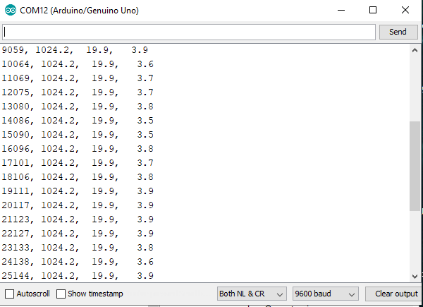
На этот раз закройте окно последовательного порта Arduino (PuTTY не откроет порт, если Arduino держит его открытым). Откройте PuTTY и нажмите «Открыть».
После этого Arduino выйдет из последовательного порта, поэтому вы должны увидеть что-то вроде этого:
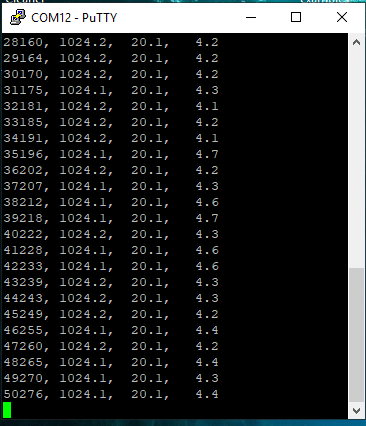
PuTTY дает вам возможность добавить или перезаписать ваш файл. После сохранения вы можете открыть файл в MS Excel.
Устройство и принцип работы потенциометра
Переменный резистор (потенциометр) поворотом ручки изменяет сопротивление в электрической цепи от нуля до номинального сопротивления в 10 кОм. Потенциометр сделан состоит из токопроводящей поверхности — плоского постоянного резистора с двумя контактами и скользящего по поверхности токосъемника. Потенциометр предназначен для точной регулировки напряжения в электрической цепи.
Со средней ножки потенциометра снимают значение напряжения
Переменный резистор имеет прочную токопроводящую поверхность, поскольку положение настройки потенциометра изменяется постоянно. Переменный резистор служит для регулярного применения, например, для изменения уровня громкости. Часто применяется в различных проектах Ардуино для начинающих.
Подстроечный резистор служит для точной настройки работы электронных устройств. Положение настройки, как правило, в течении всего срока эксплуатации устройства не изменяется. Поэтому, перемещение скользящего контакта производится с помощью отвертки, а прочность проводящего слоя не имеет большого значения.
Robot library
|
The Robot library is included with Arduino IDE 1.0.5 and later. The Robot has a number of built in sensors and actuators. The library is designed to easily access the robot’s functionality. The robot has two boards, a motor board and control board. Each board has a separate programmable processor. The library allows you to interface with the various sensors and peripherals on the control board :
The library also enables you to do a number of things with the motor board :
For more information about the Robot, visit the getting started guide and the hardware page. Library structureIt is possible to program both the Control and the Motor boards. However, it is recommended that novice programmers begin with programming the control board, leaving the motor board for later. The library exposes the sensors on both boards through a single object. There are two main classes that command the robot:
|
RobotControl classThis class commands the Control Board as well as all the I/Os and motors on the Motor Board when it has the stock firmware installed.
RobotMotor classUse this to make your own firmware for the Motor Board.
Read this document to learn about making your own firmware for the motor board using the RobotMotor class. |
Заключение
Существует много вариантов снижения энергопотребления. Подводя итог тому, что мы обсуждали до сих пор, потребление энергии Arduino можно снизить следующими методами:
- Использование режима сна и режима глубокого сна;
- Уменьшение тактовой частоты;
- Замена или удаление ненужных компонентов;
- Понижение напряжения питания на плате;
- Создание собственной Arduino.
Среди этих методов некоторые работают как по волшебству, а некоторые только в определенных ситуациях. Чтобы еще больше снизить энергопотребление ваших проектов на базе Arduino, выключайте внешние устройства, такие как SD-карты, с помощью MOSFET, когда они не используются. Кроме того, не используйте ненужные дисплеи с подсветкой или индикацией.
