Подключение sd карты к ардуино
Содержание:
- Создание файла и выбор названия для arduino SD card
- Uneven Distribution from Integer Math
- Some things to keep in mind when using the SD Library
- Библиотека ардуино для работы с SD и microSD
- Подключение SD и microSD к ардуино
- Using the SD library to retrieve information over a serial port
- Запись данных с модуля DS3231 на SD карту
- WIRING WITH ARDUINO UNO
- Что такое потенциометр и как он работает
- The Need for Calibration
- Reading the Position of a Potentiometer
- Некоторые вещи, которые необходимо учитывать при использовании библиотеки SD
- Заключение
Создание файла и выбор названия для arduino SD card
Создание файла – одна из самых распространенных задач, возникающих при работе с SD картами в ардуино. Как мы убедились в предыдущем скетче, для создания файла достаточно просто открыт его. Если мы захотим проверить, есть ли такой файл, можно использовать функцию exists():
SD.exists(“datalog.csv”);
Функция возвращает TRUE, если файл существует.
Популярной практикой при создании проектов – регистраторов данных является разбивка больших файлов на более мелкие, которые удобнее обновлять и открывать на компьютере. Например, вместо одного очень большого файла datalog.csv на SD карте можно иметь несколько маленьких, добавляя к концу номер по порядку: datalog01.csv, datalog02.csv и т.д. Вот пример скетча, который поможет вам выполнить эту работу:
Uneven Distribution from Integer Math
Consider the following example:
int v2 = map(v1, 0, 1023, 0, 1);
You would expect that values of v1 from 0 through 511 would return 0, while values above that would return 1. But this is not what happens. Instead, all values from 0–1022 return 0, and only 1023 returns 1. This is due to the map function being programmed with integer math and discarding fractions, rather than rounding them or converting to an integer after the calculation is complete.
This issue particularly affects the distribution of numbers when mapping to a small target range, and it may be a source of problems in your projects. One way to improve the distribution of values is to increase the end values of the ranges specified in the function call:
int v2 = map(v1, 0, 1024, 0, 2);
This technique still does not give perfect regularity, but values of v1 from 0 through 511 return 0, and values of 512 and above return 1, as expected.
Some things to keep in mind when using the SD Library
Overview
The communication between the microcontroller and the SD card uses the SPI protocol. This communication method is implemented on different pins depending on the board family. Classic Arduino form factor (as in Uno, Leonardo , WiFi rev2) as well as the Classic Nano, Nano Every, Nano 33 IoT, and Nano 33 BLE implement the SPI on digital pins 11, 12, and 13. The Classic large format of the Mega uses pins 50, 51, and 52. Arduino Micro uses pins 14, 15, and 16.
Additionally, another pin must be used to select the SD card. Microcontrollers implement an internal selection pin, known as SS or CS. This pin is, in most Arduino boards, pin 10, pin 53 (on the Mega), or pin 17 (on the Micro). Those are the values that will be selected by default if no other pin specified in the call to SD.begin().
The shields carrying an SD card memory slots place the SS pin differently. Please check which is the required pin for each different board and use that to call the SD.begin() function with the right parameter. Check later in the page for further information on SS pins for different shields.
Note that even if you don’t use the hardware SS pin, it must be left as an output or the SD library won’t work. Different boards use different pins for this functionality, so be sure you’ve selected the correct pin in SD.begin().
Not all the functions are listed on the main SD library page, because they are part of the library’s utility functions.
Formatting/Preparing the card
(NB : whenever referring to the SD card, it means SD and microSD sizes, as well as SD and SDHD formats)
Most SD cards work right out of the box, but it’s possible you have one that was used in a computer or camera and it cannot be read by the SD library. Formatting the card will create a file system that the Arduino can read and write to.
It’s not desirable to format SD cards frequently, as it shortens their life span.
You’ll need a SD reader and computer to format your card. The library supports the FAT16 and FAT32 filesystems, but use FAT16 when possible. The process to format is fairly straightforward.
Windows : right click on your card’s directory and choose “Format” from the drop down. Make sure you choose FAT as the filesystem.
OSX : Open Disk Utility (located in Applications>Utilities). Choose the Card, click on the erase tab, select MS-DOS(FAT) as the Format, and click Erase.
Linux: With a SD card inserted, open a terminal window. At the prompt, type , and press enter. The windows will report the device name of your SD card, it should look something like /dev/sdb1. Unmount the SD card, but leave it in the computer. Type , replacing the device name with yours. Remove the SD card and replace it to verify it works.
Opening/Closing files
When you use file.write(), it doesn’t write to the card until you flush() or close(). Whenever you open a file, be sure to close it to save your data.
As of version 1.0, it is possible to have multiple files open.
Different Shields/boards
There are a number of different shields that support SD cards. This list is not exclusive, but are commonly used.
The MEM / ENV shield
The MEM / ENV shield come with an SD card slot onboard. The shields fit on top of any Arduino MKR board (Zero, WiFi, LoRa, Sigfox, NBIoT, GSM, or Vidor). The CS pin for the SD card is on pin 4. Make sure you call SD.begin(4) to use the SD card functionality.
Arduino Ethernet Shield
The Ethernet Shield comes with an SD card slot onboard. The shield fits on top of your Arduino. Because the Ethernet module uses pin 10, the CS pin for the SD card has been moved to pin 4. Make sure you use SD.begin(4) to use the SD card functionality.
Adafruit Micro-SD breakout Board
This board supports Micro-SD cards, ans you’ll need to wire it up before you can use it. On the board, connect GND to ground, 5v to 5v, CLK to Pin 13 on your Arduino, DO to pin 12, DI to pin 11, and CS to pin 10. If you are already using pin 10, you can use a different pin, as long as you remember to change the pin in SD.begin().
Sparkfun SD Shield
The Sparkfun shield fits on your Arduino or Genuino board and uses pin 8 for CS. You will need use SD.begin(8) to use the card.
NB: the Sparkfun shield was recently updated. Older versions look similar, but were lacking a connection to the 3.3V bus and did not have the onboard hex inverter.
See Also
SD library — Your reference for the SD Card library.
- Datalogger — How to log data from three analog sensors to an SD card.
- DumpFile — How to read a file from the SD card.
- Files — How to create and destroy an SD card file.
- Listfiles — how print out the files in a directory on a SD card.
- ReadWrite — How to read and write data to and from an SD card.
- CardInfo — Get info about your SD card.
Last revision 2015/08/17 by SM
Reference Home
Библиотека ардуино для работы с SD и microSD
Для удобства работы с внешними накопителями данных в среде Arduino IDE доступны уже готовые библиотеки. Ничего дополнительно скачивать или устанавливать в большинстве случаев не понадобится.
Для подключения библиотеки в скетче нужно использовать инструкцию include:
Библиотека SPI нужна для правильной работы устройств, подключаемых по SPI.
Библиотечные функции нужно для считывания и записи данных на карту. Библиотека может поддерживать SD и SDHC карты.
Имена записываются в формате 8.3, то есть 8 знаков для названия, 3 для расширения. Путь к файлу записывается с помощью слэшей «/».
Встроенные примеры библиотеки SD
В Arduino IDE встроены готовые примеры для быстрого изучение функций бибилотеки:
Card Info – это извлечение информации, хранящейся в SD карте. С ее помощью можно узнать, в какую файловую систему отформатирована карта, наличие свободного места, какие данные записаны.
Yun Datalogger – позволяет записывать лог-данные с трех сенсоров на карту.
Datalogger – регистрирует и созраняет данные, полученные с датчика на карту.
Dump File – считывание данные с карты, передает их в серийный порт.
Files – создает и удаляет данные. Существует функция file.write(), которая помещает записанные данные в буфер
Перемещение информации на карту происходит при вызове функций flush() или close(), поэтому важно закрывать его после каждого открытия файла, иначе данные будут потеряны.
Read Write – записывает и считывает файлы с карты.
Функции библиотеки SD
Ардуино-библиотека SD содержит различные функции, с помощью которыми можно управлять данными. Функции класса SD:
begin() – функция инициализирует библиотеку, присваивает контакт для сигнала.
exists() – призвана проверить, имеется ли на карте необходимая информация.
mkdir() – позволяет создать нужную папку на карте памяти.
rmdir() – с помощью этой функции можно удалить папку
Важно, чтобы удаляемая папка была пустой.
open() – позволяет открыть файл, который нужен для записи или чтения. Если нужный файл отсутствует на карте, то он будет создан.
remove() – удаляет любой файл.
В ответ на все эти функции должно прийти одно из значений – true, в случае удачного завершения операции и false при неудаче.
Создание, редактирование и удаление файлов.
Для работы с файлами в ардуино существует класс File. В него входят функции, которые предназначены для записи и чтения информации с карты:
- available() – проверяет наличие в файле байт, которые доступны для чтения. В ответ приходит количество места, которое доступно для чтения.
- close() – закрывает файл, перед эти проверяет, сохранены ли данные на карту.
- flush() – функция позволяет убедиться, что данные записаны на карту.
- name() – возвращает указатель на имя.
- peek() – считывает байты данных, при этом не перемещает указатель на следующий символ.
- position() – находит текущее положение указателя в файле.
- print() – выводит данные в отдельный файл.
- println() – печатает данные в файл до места, где появляется символ перевода каретки и пустая строка.
- seek() – меняет положение текущей позиции в файле.
- size() – выводит информацию о размере данных.
- read() – считывает информацию.
- write() – производит запись в файл.
- isDirectory() – с помощью этого метода происходит проверка, является ли файл директорией, то есть каталогом или папкой.
- openNextFile() – выводит имя последующего файла.
- rewindDirectory() – возвращает к первому файлу в директории.
Для корректной работы платы нужно проследить, чтобы был сконфигурирован SS выход.
Подключение SD и microSD к ардуино
Существует два вида карт – microSD и SD. Они одинаковы по подключению, структуре и программе, различаются же только размером. Перед работой советуется отформатировать карту SD. Обычно новые карты уже отформатированы и готовы к работе, но если используется старая карта, то лучше провести форматирование в файловой системе Arduino. Для проведения процедуры на компьютере должна быть установлена библиотека SD, желательно FAT16. Для форматирования на Windows нужно щелкнуть на иконке карты и нажать “Format”.
Для подключения карты используется 6 контактов, взаимодействие производится по интерфейсу SPI. Она выглядит на плате как разъем на лицевой поверхности с шестью штырями. Чтобы подключить карту, нужны сам контроллер, модуль карты и 6 проводов. Помимо SPI существует режим SDIO, но он сложен в реализации и слабо совместим с Ардуино. SPI легко налаживается для работы со всеми микроконтроллерами, поэтому советуется использовать именно его.
Подключение цифровых выводов производится так: для платы Arduino Nano или Uno контакт MOSI подключается к D11, MISO к D12,SCK к D13, CS к 4, VCC на +5 В,.GND к GND. На плате имеются разъемы для подключения к 3,3 и 5 вольтам. Питание самой карты составляет 3,3 вольт, поэтому проще применять микроконтроллер с таким же питанием, в ином случае нужен преобразователей уровней напряжения. На самых распространенных платах ардуино такой выход есть.
При подключении SD карты нужно учитывать соответствие SPI контактов для разных тип плат Arduino:
| Плата | Пин MOSI | Пин MISO | Пин SCK |
| Arduino Nano, Uno | 11 | 12 | 13 |
| Arduino Mega2560 | 51 | 50 | 52 |
Using the SD library to retrieve information over a serial port
This example shows how to read a file from a SD card using the SD library and send it over the serial port. Please click here for more information on the SD library.
Hardware Required
- Arduino or Genuino board
- Ethernet Shield (or other board with an SD slot)
- Formatted SD card with a file named «datalog.txt» containing some text
Circuit
The Arduino or Genuino board has to be connected to the Ethernet Shield and also has a USB cable connected to the computer.
Code
The code below is configured for use with an Ethernet shield, which has an onboard SD slot. In the , call , naming pin 4 as the CS pin. This pin varies depending on the make of shield or board you are using.
On the SD card, there is a file named «datalog.txt». In the , the file is opened when calling . To send the file serially to a computer, use , reading the contents of the file with .
/*
SD card file dump
This example shows how to read a file from the SD card using the
SD library and send it over the serial port.
Pin numbers reflect the default SPI pins for Uno and Nano models.
The circuit:
SD card attached to SPI bus as follows:
** SDO — pin 11
** SDI — pin 12
** CLK — pin 13
** CS — depends on your SD card shield or module.
Pin 10 used here for consistency with other Arduino examples
(for MKRZero SD: SDCARD_SS_PIN)
created 22 December 2010
by Limor Fried
modified 9 Apr 2012
by Tom Igoe
This example code is in the public domain.
*/#include <SD.h>
const int chipSelect = 10;void setup() {
// Open serial communications and wait for port to open:
Serial.begin(9600);
// wait for Serial Monitor to connect. Needed for native USB port boards only:
while (!Serial);
Serial.print(«Initializing SD card…»);
if (!SD.begin(chipSelect)) {
Serial.println(«initialization failed. Things to check:»);
Serial.println(«1. is a card inserted?»);
Serial.println(«2. is your wiring correct?»);
Serial.println(«3. did you change the chipSelect pin to match your shield or module?»);
Serial.println(«Note: press reset or reopen this serial monitor after fixing your issue!»);
while (true);
}
Serial.println(«initialization done.»);
// open the file. note that only one file can be open at a time,
// so you have to close this one before opening another.
File dataFile = SD.open(«datalog.txt»);
// if the file is available, write to it:
if (dataFile) {
while (dataFile.available()) {
Serial.write(dataFile.read());
}
dataFile.close();
}
// if the file isn’t open, pop up an error:
else {
Serial.println(«error opening datalog.txt»);
}}void loop() {}
See Also
- SD library — Your reference for the SD Card library.
- Notes on using SD cards – What you need to know when you use SD cards
- CardInfo — Get info about your SD card.
- Datalogger — How to log data from three analog sensors to an SD card.
- Files — How to create and destroy an SD card file.
- Listfiles — How print out the files in a directory on a SD card.
- ReadWrite — How to read and write data to and from an SD card.
Last revision 2015/08/18 by SM
Запись данных с модуля DS3231 на SD карту
Необходимые детали:► Arduino UNO R3 x 1 шт.► Модуль micro SD карт, SPI x 1 шт.► Часы реального времени DS3231 x 1 шт. ► Провод DuPont, 2,54 мм, 20 см, F-M (Female — Male) x 1 шт.► Кабель USB 2.0 A-B x 1 шт.
ПодключениеВ примере используем модуль micro SD карты и часы реального времени DS3231, с последнего будем считывать время и показания температуры (раз в три сукунды). Схема не сложная, собираем согласно рисунку ниже.

Для работы скетча необходимо три библиотеки «SD«, «SPI» и «DS3231» последняя библиотека не входит в среду разработки IDE Arduino, необходимо дополнительно установить ее, скачать можно конце статьи.
/*
Тестировалось на Arduino IDE 1.8.5
Дата тестирования 15.02.2019г.
*/
#include <SD.h> // Подключаем библиотеку SD
#include <SPI.h> // Подключаем библиотеку SPI
#include <DS3231.h> // Подключаем библиотеку DS3231
File myFile;
DS3231 rtc(SDA, SCL);
const int chipSelect = 4; // Указываем к какому выводу подключен CS
void setup()
{
Serial.begin(9600); // Открытие последовательную связь
if (SD.begin())
{
Serial.println(«SD card is ready to use.»);
}
else
{
Serial.println(«SD card initialization failed»);
return;
}
rtc.begin();
}
void loop() {
Serial.print(rtc.getTimeStr()); // Печатаем считанное показания времени
Serial.print(«,»); // Печатаем символ «,»
Serial.println(int(rtc.getTemp())); // Печатаем считанное показания температуры
myFile = SD.open(«test.txt», FILE_WRITE); // Открытие файла, одновременно может быть открыт только один файл
if (myFile) {
myFile.print(rtc.getTimeStr()); // Запись текста в файл.
myFile.print(«,»); // Запись текста в файл.
myFile.println(int(rtc.getTemp())); // Запись текста в файл.
myFile.close(); // Закрываем файла
}
else {
Serial.println(«error opening test.txt»); // Печатаем текст, если не удалось открыть файл
}
delay(3000); // Пауза 3с
}
|
1 2 3 4 5 6 7 8 9 10 11 12 13 14 15 16 17 18 19 20 21 22 23 24 25 26 27 28 29 30 31 32 33 34 35 36 37 38 39 40 41 42 43 44 |
/* */ File myFile; DS3231 rtc(SDA,SCL); constintchipSelect=4;// Указываем к какому выводу подключен CS voidsetup() { Serial.begin(9600);// Открытие последовательную связь if(SD.begin()) { Serial.println(«SD card is ready to use.»); } else { Serial.println(«SD card initialization failed»); return; } rtc.begin(); } voidloop(){ Serial.print(rtc.getTimeStr());// Печатаем считанное показания времени Serial.print(«,»);// Печатаем символ «,» Serial.println(int(rtc.getTemp()));// Печатаем считанное показания температуры myFile=SD.open(«test.txt»,FILE_WRITE);// Открытие файла, одновременно может быть открыт только один файл if(myFile){ myFile.print(rtc.getTimeStr());// Запись текста в файл. myFile.print(«,»);// Запись текста в файл. myFile.println(int(rtc.getTemp()));// Запись текста в файл. myFile.close();// Закрываем файла } else{ Serial.println(«error opening test.txt»);// Печатаем текст, если не удалось открыть файл } delay(3000);// Пауза 3с } |
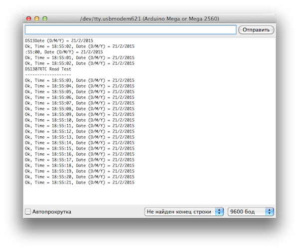
После загрузки скетча Arduino начнет сохранять значения температуры каждые 3 секунды.

Теперь, через некоторое время можно подключить SD карту к компьютеру и открыть файл «TEST.txt», чтобы увидеть результаты.

При необходимости можно создать линейный график.
Ссылки Библиотека libraries-DS3231
Купить на Aliexpress Контроллер Arduino UNO R3 на CH340G Контроллер Arduino UNO R3 на Atmega16U2 Провода DuPont, 2,54 мм, 20 см Модуль SD кары, SPI Часы реального времени RTC DS3231
WIRING WITH ARDUINO UNO
Even though the microSD card has 8 pins, we need only 6 pins to interface it using SPI and thus has 6 header pins soldered on it. There are two supply pins — VCC and GND. VCC is connected to 5V and the on-board low drop regulator AMS1117 will provide 3.3V to the card and the buffer IC 74LVC125. The MISO (Master Input Slave Output), MOSI (Master Output Slave Input) and SCK (Serial Clock) are connected to the respective pins of the microcontroller. The CS (Chip Select) is connected to the Slave Select (SS) of the microcontroller. In fact, you can use any digital pins to connect to the module and bit-bang the SPI protocol using any library. But it’d be better to use the hardware SPI for some reasons. I’ve provided a wiring schematic below and to make it easy for you, the wiring procedure in steps too. If you’re using another Arduino model, just use the respective pins. Connect,
- VCC of module to 5V of Arduino.
- GND of module to GND of Arduino.
- CS to digital pin 10 of Uno.
- MOSI to digital pin 11 of Uno.
- MISO to digital pin 12.
- SCK to digital pin 13.
Wiring diagram for interfacing Catalex Micro SD Card adapter with Arduino Uno — View PDF or Download Eagle File
In Arduino Uno, the digital pin 10 (pin 16 of ATmega328P) is the dedicated Slave Select (SS) pin. But you could connect the CS of the module to any digital pin of the Uno by initiating the card with . The SdFat library we’ll be using needs the digital pin 10 (SS pin on Arduino) to set as output, because the SS will be still manipulated when hardware SPI is used. So changing its state to digital output might disable the SPI. There will be usually a Chip Detect (CD) pin from the SD card slot. But unfortunately this Catalex module doesn’t have a CD output. So that’s all about the wiring. Here’s a pinout of an ATmega8/168/328 if you are confused.
Что такое потенциометр и как он работает
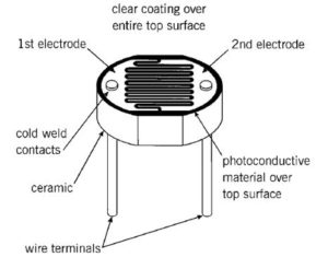
Потенциометр – это регулируемый делитель электрического напряжения (переменный резистор). Он представляет собой резистор с подвижным контактом.
Чаще всего потенциометры используют для управления громкостью звука а также для управления яркостью освещения.
Давайте теперь поговорим о том, как это работает. У потенциометра есть 3 вывода: плюс (5В), минус (земля) и аналоговый вход. На анимационной картинке выше можно видеть как выглядит рабочий потенциометр внутри. На один крайний вывод мы получаем 5В, а на второй крайний вывод у нас идёт минус. Когда мы крутим ручку потенциометра, то ротор вращается по резистивном веществе. Средний вывод у нас — это аналоговый вывод. Когда ручка находиться в начальном положении то на аналоговый вывод поступает минимальное число. Очевидно что чем дальше мы проворачиваем ручку тем большее число мы получаем на выходе.
The Need for Calibration
The circuit and code above are convenient when each side of the potential divider is equal (a maximum 10Ko from the pot, and 10Ko from the fixed resistor). However, when using a different value pot or fixed resistor, the values read by the Arduino will not be so perfect.
Using a 470Ko potentiometer unbalances the potential divider formed with the 10Ko resistor and, to further complicate matters, not all pots are constructed equally. The 470Ko pot used while testing this circuit actually has a maximum resistance of 560Ko.
To (approximately) determine the value of the pot in these situations, you need to know the start and end values that are actually read by the Arduino. One way to do this is to write a short sketch that outputs the results of calls to analogRead, so that you can turn the pot from left to right and record the minimum and maximum values.
/*
 *
 * Udemy.com
 * Numeric Distribution with Arduino's Map Function
 *
 */
 // pin assignments
 int POT = 0;
 // initialize the serial port
 void setup() {
   Serial.begin(9600);
 }
 // read from the analog input connected to the pot
 // and print the value to the serial port.
 // the delay is only to avoid sending so much data
 // as to make it unreadable.
 void loop() {
   int v = analogRead(POT);
   Serial.println(v);
   delay(1000);
 }
With the “470Ko” pot, the values range from 0 through 912, not 0 to 1023. So you can map the values read by analogRead to the resistance range of the actual pot by using the following call:
int v2 = map(v1, 0, 912, 0, 560000);
The rotation of the pot would be calculated similarly:
int r = map(v1, 0, 912, -135, 135);
Reading the Position of a Potentiometer
In the circuit shown below, a 10Ko potentiometer (“pot”) is connected to the Arduino’s analog input pin 0, and forms a potential divider with the 10Ko fixed resistor. Conveniently, the Arduino’s ADCs can read the voltage level using the full range of values 0 through 1023.
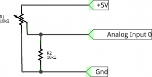
Potentiometers often turn through 270° from the far left position to the far right, and are popularly used in volume knobs and amplifiers with the numbers 1–10 written around them. To get the value of the pot in terms of the positions 1–10, you can map the reading to that range:
int v2 = map(v1, 0, 1024, 1, 11);
Note that this example suffers heavily from the same distribution problem as mentioned above, and so the end values of the ranges have been incremented. This amp does not go to 11.
You can also approximate the position of the pot (in terms of its rotation):
int r = map(v1, 0, 1023, 0, 270);
Many people would regard the 0° position to be in the center – not the far left as used in the preceding example – with the knob’s position marker pointing straight up. Thinking this way, the angles of rotation of the pot are -135° through 135°. The map function does not require that all values are positive, so the following call can be used to map the value to a range indicating the knob’s position with 0° as the center:
int r = map(v1, 0, 1023, -135, 135);
Некоторые вещи, которые необходимо учитывать при использовании библиотеки SD
Обзор
Связь между микроконтроллером и SD картой использует интерфейс SPI, который занимает цифровые выводы 11, 12 и 13 (на большинстве плат Arduino) или 50, 51 и 52 (Arduino Mega). Кроме того, для выбора SD карты должен использоваться еще один дополнительный вывод. Это может быть аппаратный вывод SS – вывод 10 (на большинстве плат Arduino) или вывод 53 (на платах Arduino Mega) – или какой-либо другой вывод, заданный с помощью вызова
Обратите внимание, что даже если вы не используете аппаратный вывод SS, он должен быть оставлен настроенным для работы на выход, иначе библиотека SD работать не будет. Разные платы расширения для этого используют разные выводы, поэтому убедитесь в правильности выбора вывода в
Форматирование/подготовка карты
Примечание: всякий раз, когда в данной статье упоминается SD карта, это означает и SD, и microSD размеры, а также SD и SDHD форматы.
Большинство SD карт работает правильно сразу из коробки, но, возможно, ваша карта использовалась в компьютере или камере и не может быть прочитана с помощью библиотеки SD. Форматирование такой карты создаст файловую систему, в которой Arduino сможет читать и писать.
Часто форматировать SD карты нежелательно, так как это уменьшает их срок службы.
Для форматирования карты вам понадобятся SD ридер и компьютер. Библиотека поддерживает файловые системы FAT16 и FAT32, но по возможности лучше используйте FAT16.
Именование файлов
Файловые системы FAT имеют ограничения, когда в них используются соглашения по именованию файлов. Вы должны использовать формат 8.3, в котором имена файлов выглядят так «NAME001.EXT«, где «NAME001» – строка из 8 или менее символов, а «EXT» – расширение из 3 символов. Люди часто используют расширения .TXT и .LOG. Возможно использовать и более короткие имена (например, mydata.txt или time.log), но более длинные имена файлов использовать запрещается.
Открытие/закрытие файлов
Когда вы используете , то на карту ничего не будет записано, пока вы не вызовете или . Всякий раз, когда вы открываете файл, убедитесь, что закрыли его, чтобы сохранить свои данные.
Начиная с версии 1.0, стало возможно иметь открытыми сразу несколько файлов.
Различные платы расширения
Ниже приведено несколько различных плат расширения, поддерживающих SD карты. Этот список неполный, но в нем приведены наиболее часто используемые платы.
Arduino Ethernet Shield
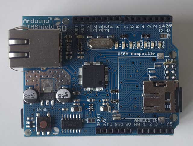 Arduino Ethernet Shield
Плата расширения Ethernet Shield поставляется со слотом для SD карты. Плата устанавливается на Arduino сверху. Поскольку Ethernet модуль использует вывод 10, вывод CS для SD карты был перемещен на вывод 4. Для использования функционала SD карты вызывайте метод .
Adafruit Micro-SD breakout Board
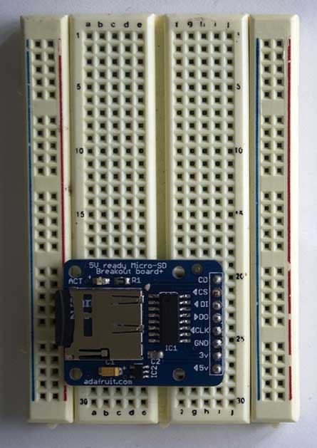 Adafruit Micro-SD breakout Board
Данная плата поддерживает Micro-SD карты. Перед использованием ее необходимо правильно подключить к Arduino. Вывод GND на плате соедините с шиной земли на Arduino, вывод 5V – с шиной 5V, CLK – с выводом 13 на Arduino, DO – с выводом 12, DI – с выводом 11, CS – с выводом 10. Если вы уже используете вывод 10, то можете к CS подключить другой вывод, но не забудьте изменить вывод в .
Sparkfun SD Shield
 Sparkfun SD Shield
Плата расширения Sparkfun устанавливается на Arduino сверху и использует вывод 8 для CS. При использовании SD карты вам необходимо вызвать метод .
Заключение
Как мы с вами убедились, подключить SD карту памяти к Ардуино и использовать ее в проекте не очень сложно. Для этого есть готовые библиотеки в Arduino IDE и самые разнообразные варианты модулей. Приобрести карту памяти можно в любом магазине электроники, они стоят недорого, при этом позволяют существенно расширить потенциал платы Ардуино. С использованием карт памяти можно собирать и сохранять для последующего анализа большие объемы данных. С помощью нашей статьи мы сможете наделить памятью свои исследовательские проекты, создать системы голосового оповещения для умного дома, создать простой wav-проигрыватель и многое другое.
