Пид-регулятор своими руками
Содержание:
Характеристики и подключение датчиков DHT11 и DHT22
Датчик состоит из двух частей – емкостного датчика температуры и гигрометра. Первый используется для измерения температуры, второй – для влажности воздуха. Находящийся внутри чип может выполнять аналого-цифровые преобразования и выдавать цифровой сигнал, который считывается посредством микроконтроллера.
В большинстве случаев DHT11 или DHT22 доступен в двух вариантах: как отдельный датчик в виде пластикового корпуса с металлическими контактами или как готовый модуль с датчиком и припаянными элементами обвязки. Второй вариант гораздо проще использовать в реальных проектах и крайне рекомендуется для начинающих.
Датчик DHT11
- Потребляемый ток – 2,5 мА (максимальное значение при преобразовании данных);
- Измеряет влажность в диапазоне от 20% до 80%. Погрешность может составлять до 5%;
- Применяется при измерении температуры в интервале от 0 до 50 градусов (точность – 2%)
- Габаритные размеры: 15,5 мм длина; 12 мм широта; 5,5 мм высота;
- Питание – от 3 до 5 Вольт;
- Одно измерение в единицу времени (секунду). То есть, частота составляет 1 Гц;
- 4 коннектора. Между соседними расстояние в 0,1 ”.
Датчик DHT22
- Питание – от 3 до 5 Вольт;
- Максимальный ток при преобразовании – 2,5 мА;
- Способен измерять влажность в интервале от 0% до 100%. Точность измерений колеблется от 2% до 5%;
- Минимальная измеряемая температура – минус 40, максимальная – 125 градусов по Цельсию (точность измерений – 0,5);
- Устройство способно совершать одно измерение за 2 секунд. Частота – до 0,5 ГЦ;
- Габаритные размеры: 15,1 мм длина; 25 мм широта; 5,5 мм высота;
- Присутствует 4 коннектора. Расстояние между соседними – 0,1 ‘;
Очевидно, что при использовании в ардуино датчика температуры и влажности DHT11 устройство выдаст менее точные значения, чем DHT22. У аналога больший диапазон измеряемых значений, но и цена соответствующая. Датчик температуры и влажности DHT22, как и его аналог, имеет один цифровой выход, соответственно снимать показания можно не чаще, чем один раз в 1-2 секунды.
Platform Independence
This library was built with versatility in mind. Though the project it was
built for is Arduino, no Arduino-specific function calls are made. Instead,
function pointers provide hooks for gathering necessary inputs, such as system
time.
PID Source, Output, and other Hooks
Since one of the primary focuses in this library is platform independence, there
are several instances where function pointers are used to provide hooks into the
parent program. Three notable instances are:
The and are used for retrieving from the
parent system and delivering the calculated , respectively. At the
construction of a , two function pointers are passed in which
represent functions created by the user which perform these tasks. Below is an
example of using and functions:
int pidSource()
{
  return mySensor.getValue();
}

void pidOutput(int output)
{
  myRobot.driveAtSpeed(output);
}

// P, I, and D represent constants in the user's program
PIDController myPIDController(P, I, D, pidSource, pidOutput);
is a method that gives the user a chance to tell the
how to retrieve system time. This is useful because different
platforms have different APIs but we can use handling functions to pass in
references to time-getting functions (if the return type matches the
‘s function pointer type) or to make conversions so that the
types are made to match. Below are some examples:
On an Arduino system, the millis() function returns time in milliseconds
as an unsigned long, which matches the function pointer type for
the registerTimeFunction() method.
On a system that has no matching time-getting function, we can create a
wrapper method that will convert the value and allow us to pass it as a
parameter.
// Let's assume this platform's time function is
// double getSeconds();

unsigned long timeFunction()
{
  // Multiply by 1000 to convert seconds to milliseconds
  return (unsigned long) (getSeconds() * 1000);
}

myPIDController.registerTimeFunction(timeFunction);
HowTo Control devices with PIDLibrary — #arduSerie 23
J3Follow
Dec 25, 2016 · 4 min read
Hi, this is the goal: we have to control the speed of an exhaust fan by the pid method. We will use the Arduino PID Library by Brett Beauregard and Front-End v03 using Processing.org version 3.1.
We capture the fan speed by means of an Reflective IR Sensor with 330R and 100K Resistors.
The reading is done on the 16 x 2 lcd. We are using adapter LCM1602 IIC.
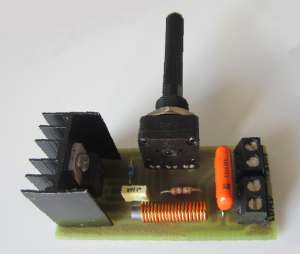
For tests we use the potentiometer to print the desired speed. Then with the project complete we use the interface made by Brett Beauregard. It’s a piece of cake!!!

Before going deeper into the study, let’s start with the very simple: experiment with a dark tube and measure the amount of light incident on ldr.
Please, watch the video to understand the procedure well:
The idea is simple: an input, processing, output, feedback, correction erros and start all over again…
Realize that the input is analog (LDR) — normally is — and the output is digital (in the case pwm for control of light of the led)
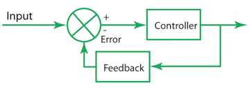
In a simple way, the errors are calculated and the correction is delivered to the system actuator.
The same thinking for the whole system. This time the input is the RPM speed of the exhaust fan and the output is the replacement of the middle pin of the potentiometer. See the main code.
To get to the final code we walk a path marked by the Sketches published on my github from 1 to 7. Look:
(Sketch 01)_23_arduSerie_ArduTachoMeterV2_I.ino
Start code: read the speed of an independent motor running outside circuit on the serial terminal;
(Sketch 02)_23_arduSerie_ArduTachoMeterV2_II.ino
Instead of reading in the serial terminal insert the 16X2 lcd in the circuit and sends the reading to the screen; onward!!!
(Sketch 04)_23_arduSerie_ArduTachoMeterV2_IV.ino
Working with the motor. A simple program of speed control without the use of potentiometer. Based on Jeremy Blum’s book.
(Sketch 05)_23_arduSerie_ArduTachoMeterV2_V.ino
We modified the program of Jeremy Blum to insert in the circuit the control of the speed with the potentiometer. All the codes are functional and tend to the final result;
(Sketch 06)_23_arduSerie_ArduTachoMeterV2_VI.ino
The code already sends the data to the lcd and the control is done by the potentiometer in the analog input pin A0 and the output pwm in pin 9 of the arduino. We are very close to the ultimate goal;
(Sketch 07)_23_arduSerie_ArduTachoMeterV2_VII.ino
Final result: we read the speed of the fun via lcd and the code communicates with the processing v3.1 using the serial port (the protocol are implemented).
We are using the Arduino PID Library by Brett Beauregard and Front-End v03 using Processing.org version 3.1.
Input = rpm; myPID.Compute(); analogWrite(outputPin, Output);
This is the main part of the code. We have to send an input and receive the output calculated by Brett’s library. Is a reusable code. Realize that we have adapted the initial scketch to our specifications: the maximum calculated speed of 3500 rotations and the reading and mapped to 8 bits.
Thanks for the visit. Watch the video to learn more about the steps and the end result and until the next implementation. Bye!!!
PID Control — A brief introduction by Brian Douglas
Controlling temperature with a PID controller
15º Lego Episode — PID — The Ultimate Line Follower — Algorithm for your EV3 PID Line Follower Robot
5 /5 Part JayThree Balancing Car Project —PID without a PhD
X. Подводные камни.
Учет размерностей
Самое важное, и самая частая ошибка. Нельзя просто взять U=K*(Err+Ki*Int+Kd*Diff), без оговаривания ЧТО есть K, Ki, Kd
И с какой точностью. Особенно важно для коэффициента Ki, который имеет размерность обратную времени — если операция идёт в целых числах, НЕЛЬЗЯ просто умножать на него — так как там должно быть ДЕЛЕНИЕ, а обратное число в целых числах не представимо.
Учет знака. Второе очень важное — учет знака. Все операции должны быть знаковыми, интеграл обязан накапливаться знаковый — так как он не только замещает пропорциональную составляющую, но и позволяет сопротивляться внешним воздействиям, например — выделению тепла самой смеси; и тогда его знак отрицательный.
Учет переполнения. Нам важно получить либо мощность от 0% до 100%, либо факт того, что вычисленная мощность больше 100% или меньше 0%. Нет нужды производить все вычисления, если мы получили отрицательный подскобочный результат, например. Но при этом важно учесть, что при произведении-сложении может произойти переполнение — и его нужно учесть как «больше 100%», а ни в коем образе не оставить результат после переполнения. Это чревато в первую очередь отсутствием регулирования когда требуется — объект ниже требуемой температуры, а мощность не подаётся
Учет времени вычислений. Необходимость великоразрядных умножений (при кривой реализации — еще и деления) требует времени, поэтому крайне важно просчитать время выполнения самого худшего варианта вычислений, и оно должно быть меньше, чем свободное время между измерениями. Невыполнение этого условия ведёт к неуправляемому объекту, который «вроде работает, но как-то не так
Integeral Windup
Applications that control slow moving systems and have a non-zero integral term often see significant overshoot on startup.
This is caused by the integral sum «winidng up» as it remembers a long time away from the setpoint. If this describes your
system there are two things you can do.
Addressing Windup: Limit the Sum
There are constants in that control the maximum allowable integral. Lowering these prevents the controller from
remembering as much offset from the setpoint and will reduce the overshoot.
#define INTEG_MAX    (INT32_MAX)
#define INTEG_MIN    (INT32_MIN)
Change these constants with caution. Setting them too low will fix your overshoot problem but it will negatively affect
the controller’s ability to regulate the load. If you’re unsure of the right constant use the next solution instead of
limiting the sum.
Limiting Windup: Bounded Regulation
The PID controller works best when the system is close to the setpoint. During the startup phase, or in the case of a
significant excursion, you can disable PID control entirely. An example of this can be found in the Sous-Vide controller
example in this project. The core of the logic is in this code:
if (feedback < (setpoint * 0.9)) {
  analogWrite(PIN_OUTPUT, 1);
  myPID.clear();
}
else {
  analogWrite(PIN_OUTPUT, myPID.step(setpoint, feedback));
}
The code bypasses the PID when the temperature is less than 90% of the setpoint, simply turning the heater on. When the
temperature is above 90% of the setpoint the PID is enabled. Fixing your overshoot this way gives you much better control
of your system without having to add complex, invalid and difficult to understand features to the PID controller.
Commands to send to the arduino
The following are examples of commands that can be submitted to handle_cmd():
- — does a text dump of various variables.
- — write variables kP, kI, and kD to the eeprom
- — dump all eeprom variables out as text
- — restore the current kP, kI, and kD variables from what’s in eeprom.
- — sets kP to 10.0
- — sets kI to 0.002
- — sets kD to 1.0
- — sets the target to 100
- — sends data to the python program for graphing
- — pause the motor.
- — sets the encoder counter to zero.
- — returns a name for the device, in this case «PID_device». I like this when multiple devices are hanging off the same computer, then my python code can poll all the devices and find the one it’s interested in.
Note: you can use all of those commands in the serial terminal of the arduino IDE. To give it a try go to Tools—>serial monitor.
Moving on. The function is not particularly interesting. The function cal handles retrieving the variables , , and from the eeprom. The function looks like this:
Hopefully you’re familiar with state machines. These are really handy if you get tired of having . There are some super fast programs for things like balancing robots that use state machines. The basis of this section is the switch statement. Where:
The most relevant section of the loop is:
When state = S_MOTOR_INIT we’ll clear the positionArray[] that will be used log our position data, pass our current kP, kI, kD values to the PID function, and then change the state to S_MOTOR_RUN. When we’re in S_MOTOR_RUN we do a very simple set of things:
- find position with
- compute the PID with `myPID.Compute();
-
can range from -255 to +255
- set direction of the motors based if if output is < 0,
- set the motor’s speed with
- then log the position in positionArray[]
That’s PID control! Pretty darn simple.
We stay in S_MOTOR_RUN state until another command is issued to the program.
API
The API strives to be simple and clear. I won’t implment functions in the controller that would be better implemented outside of the controller.
FastPID()
Construct a default controller. The default coefficients are all zero. Do not use a default-constructed controller until after you’ve called and
FastPID(float kp, float ki, float kd, float hz, int bits=16, bool sign=false)
Construct a controller that’s ready to go. Calls the following:
configure(kp, ki, kd, hz, bits, sign);
bool setCoefficients(float kp, float ki, float kd, float hz);
Set the PID coefficients. The coefficients and are scaled by the value of . The value informs the PID of the rate you will call . Calling code is responsible for calling at the rate in . Returns if a configuration error has occured. Which could be from a previous call.
bool setOutputConfig(int bits, bool sign);
Set the ouptut configuration by bits/sign. The ouput range will be:
For signed equal to
2^(n-1) — 1 down to -2^(n-1)
For signed equal to
2^n-1 down to 0
Bits equals 16 is a special case. When bits is and sign is the output range is
32767 down to 0
Returns if a configuration error has occured. Which could be from a previous call.
bool setOutputRange(int16_t min, int16_t max);
Set the ouptut range directly. The effective range is:
- Min: -32768 to 32766
- Max: -32767 to 32767
Min must be greater than max.
Returns if a configuration error has occured. Which could be from a previous call.
void clear();
Reset the controller. This should be done before changing the configuration in any way.
bool configure(float kp, float ki, float kd, float hz, int bits=16, bool sign=false);
Bulk configure the controller. Equivalent to:
clear();
setCoefficients(kp, ki, kd, hz);
setOutputConfig(bits, sign);
int16_t step(int16_t sp, int16_t fb);
Run a single step of the controller and return the next output.
bool err();
Test for a confiuration error. The controller will not run if this function returns .
Code for fixed PID control
Ok so the code below is a bit large. But don’t worry. It is very easy. We set a variable setpoint at 100 degrees for this example. Then we read the thermocouple real temperature value as in the past example. Then we use 3 constants and calculate the PID sum. Depending on that value we create a PWM signal on pin D3 and apply it to the MOSFET gate using a BJT driver.
Download PID code without control here:

As you can see the temperature stays at that value. But that is after trying a lot of PID constants and that is the tricky part of this project. So, what you will have to do is try your own values till you get the correct ones. I advise you to start with the I and D values equal 0 and then increase those values slowly till you get good results.
Here on my oscilloscope I have the PWM signal of the MOSFET connected.

At the beginning, till the system reaches the desired value the pulse has a small width since I use a BJT to activathe the N channel gate, so the mosfet is activated with a LOW value in this case. Once the set value is reached it starts to wambble around and by that maintaining the temperature. As you can see, if I try to cool down the heating element by blowing air with this tube, the PWM signal width get’s lower in order to keep the same value. So, the control works.
VIII. Вычисление воздействия
U — мощность, которую следует выдать;
K — пропорциональный коэффициент (обратите внимание — вынесен за скобки, почему — чуть ниже опишу);
Ti — постоянная времени интегрирования. Обратите внимание — в расчетах используется обратная величина;
Td — постоянная времени дифференцирования
Err — текущее рассогласование (разница между уставкой и измеренной температурой
dErr — производная рассогласования (разница между текущей и прошлой ошибкой)
Int — накопленный интеграл рассогласования (сумма всех Err’ов, кои мы видели). IIIприборфизическим
IIIприборфизическим
- U — имеет величину в % мощности. Еще точнее — в 2/5 от % мощности, так как у нас таблица идёт через 1/250 от 100%.
- Err — рассогласование, задаётся в градусах. Точнее — через 1/32 градуса.
- Int — интеграл, представляет собой сумму градусов во времени — а значит, имеет размерность градус*сек. Точнее — (1/32 градуса)*(1/25 сек)
- Ti — задаётся через 1/25 сек
- (1/Ti)*Int — после вычисления даёт вклад, имеющий размерность (1/32 градуса).
- dErr — производная, имеет размерность градус/сек, а точнее (1/32 градуса)/(1/25 сек)
- Td — задаётся через 1/25 сек
- Td*dErr — после произведения приводит вклад к размерности (1/32 градуса)
- (…) — итак, все слагаемые под скобками приведены к размерности (1/32 градуса)
- K — согласует U и (…), а значит имеет размерность процента-на-градус, точнее (2/5)%/(1/32 градуса)
Ti1/TiDivision by Invariant Integers using MultiplicationKTiTdTiTi_mTi_sh1Ti_sh2
- ; Нам нужна прошла ошибка. Ошибки — по 16бит
- ; Вычисляем новое рассогласование. 16bit
- ; Интегрируем ошибку. При этом считаем полусумму разности (разностная схема). 32bit = 32bit + 16bit
- ; Считаем интегральный вклад — 32bit * 32bit => 32bit
- ; Считаем диф вклад — 16*16 => 32bit
- ; Подскобочное; 16+32+32 => 32bit
- ; Коэфф; 32*16/8 bit => 40bit.