Datasheet atmega128a-au — atmel даташит 8- бит микроконтроллеры (mcu) 128k flash 4k eeprom 4k sram 53 io pins
Содержание:
Getting started with MegaCore
Ok, so you’re downloaded and installed MegaCore, but how to get started? Here’s a quick start guide:
- Hook up your microcontroller as shown in the .
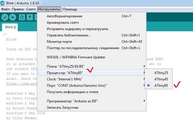
- Open the Tools > Board menu item, and select ATmega64, ATmega128, ATmega1281, ATmega2561, ATmega640, ATmega1280, ATmega2560, AT90CAN32, AT90CAN64 or AT90CAN128.
- Select your preferred clock frequency. 16 MHz is standard on most Arduino boards.
- Select what kind of programmer you’re using under the Programmers menu.
- Hit Burn Bootloader. If an LED is connected to pin PB5/PB7, it should flash twice every second.
- Now that the correct fuse settings is sat and the bootloader burnt, you can upload your code in two ways:
- Disconnect your programmer tool, and connect a USB to serial adapter to the microcontroller, like shown in the . Then select the correct serial port under the Tools menu, and click the Upload button. If you’re getting some kind of timeout error, it means your RX and TX pins are swapped, or your auto reset circuity isn’t working properly (the 100 nF capacitor on the reset line).
- Keep your programmer connected, and hold down the button while clicking Upload. This will erase the bootloader and upload your code using the programmer tool.
Your code should now be running on the microcontroller!
Загрузчик для ATmega128A
Для того, чтобы записать программу в память микроконтроллера непосредственно из Arduino IDE потребуется специальная программа-загрузчик (bootloader), размещенная в специальной области памяти микроконтроллера, которая постоянно опрашивает UART.
Это немного измененная версия загрузчика с сайта www.chip45.com.
Bootloader Mega128 bootloader_mega128.zip
10.0 KiB 1738 Downloads
| Category: | Programs |
| Date: | 27.10.2015 |
Для компиляции я использовал AVR-GCC.
$ avr-gcc -mmcu=atmega128 -Wall -Os -o boot_mega128.o boot_mega128.c
$ avr-objcopy -O ihex boot_mega128.o boot_mega128.hex
|
1 2 |
$avr-gcc-mmcu=atmega128-Wall-Os-oboot_mega128.oboot_mega128.c $avr-objcopy-Oihex boot_mega128.oboot_mega128.hex |
В архиве содержится исходный C-файл, объектый файл и готовый hex-файл. Для дальнейших действий понадобится только последний.
Устанавливаем фьюзы микроконтроллера и прошиваем загрузчик, используя программатор USBasp и AVRDUDE:
$ sudo avrdude -p m128 -c usbasp -P usbasp -Uefuse:w:0xff:m -Uhfuse:w:0xca:m -Ulfuse:w:0xff:m -Ulock:w:0x3F:m
$ sudo avrdude -p m128 -c usbasp -e -U flash:w:boot_mega128.hex -Ulock:w:0x0F:m
|
1 2 |
$sudo avrdude-pm128-cusbasp-Pusbasp-Uefusew0xffm-Uhfusew0xcam-Ulfusew0xffm-Ulockw0x3Fm $sudo avrdude-pm128-cusbasp-e-Uflashwboot_mega128.hex-Ulockw0x0Fm |
В Windows sudo писать не нужно.
Создадим папку atmega128 и перепишем в нее файл boot_mega128.hex в папке с загрузчиками среды Arduino для того, чтобы можно было прошивать bootloader прямо из Arduino IDE.
В MacOS X путь к папке с загрузчиками выглядит следующим образом:
.../arduino/Contents/Java/hardware/arduino/avr/bootloaders
Файл boards.txt
В Windows этот файл расположен в папке с Arduino:
.../hardware/arduino/avr/boards.txt
В Mac OS X:
.../arduino/Contents/Java/hardware/arduino/avr/boards.txt
В конец файла boards.txt среды Arduino добавляем следующие строчки:
###############################################################
atmega128A.name=Custom ATmega 128 Breakout Board using AVRISP
atmega128A.upload.tool=usbasp
atmega128A.upload.maximum_size=126976
atmega128A.bootloader.low_fuses=0xFF
atmega128A.bootloader.high_fuses=0xCA
atmega128A.bootloader.extended_fuses=0xFF
atmega128A.bootloader.path=atmega
atmega128A.bootloader.file=boot_mega128.hex
atmega128A.bootloader.unlock_bits=0x3F
atmega128A.bootloader.lock_bits=0x0F
atmega128A.build.mcu=atmega128
atmega128A.build.f_cpu=8000000L
atmega128A.build.core=arduino
atmega128A.build.variant=mega128
|
1 2 3 4 5 6 7 8 9 10 11 12 13 14 15 16 17 18 |
############################################################### atmega128A.name=Custom ATmega128Breakout Board using AVRISP atmega128A.upload.tool=usbasp atmega128A.upload.maximum_size=126976 atmega128A.bootloader.low_fuses=0xFF atmega128A.bootloader.high_fuses=0xCA atmega128A.bootloader.extended_fuses=0xFF atmega128A.bootloader.path=atmega atmega128A.bootloader.file=boot_mega128.hex atmega128A.bootloader.unlock_bits=0x3F atmega128A.bootloader.lock_bits=0x0F atmega128A.build.mcu=atmega128 atmega128A.build.f_cpu=8000000L atmega128A.build.core=arduino atmega128A.build.variant=mega128 |
Обратите внимание на фьюзы загрузчика. Они в точности должны совпадать с указанными при его прошивке!. Тактовая частота микроконтроллера у меня установлена равной 8 МГц
Тактовая частота микроконтроллера у меня установлена равной 8 МГц.
Hello, world!
Осталось проверить работоспособность. Подключаем к выводу PB4 светодиод (12 пин) и наслаждаемся его незамысловатым миганием, предварительно загрузив представленный ниже скетч в микроконтроллер, выбрав микроконтроллер Custom ATmega 128 Breakout Board using AVRISP и программатор USBasp из среды Arduino IDE.
int ledPin=12;
void setup() {
pinMode(ledPin, OUTPUT);
}
void loop() {
digitalWrite(ledPin, HIGH);
delay(1000);
digitalWrite(ledPin, LOW);
delay(1000);
}
|
1 2 3 4 5 6 7 8 9 10 11 12 |
intledPin=12; voidsetup(){ pinMode(ledPin,OUTPUT); } voidloop(){ digitalWrite(ledPin,HIGH); delay(1000); digitalWrite(ledPin,LOW); delay(1000); } |
Datasheets
Features
• High-performance, Low-power AtmelAVR8-bit Microcontroller
• Advanced RISC Architecture • • • • • •
•
• — 133 Powerful Instructions — Most Single Clock Cycle Execution
— 32 x 8 General Purpose Working Registers + Peripheral Control Registers
— Fully Static Operation
— Up to 16MIPS Throughput at 16MHz
— On-chip 2-cycle Multiplier
High Endurance Non-volatile Memory segments
— 128Kbytes of In-System Self-programmable Flash program memory
— 4Kbytes EEPROM
— 4Kbytes Internal SRAM
— Write/Erase cycles: 10,000 Flash/100,000 EEPROM
— Data retention: 20 years at 85°C/100 years at 25°C(1)
— Optional Boot Code Section with Independent Lock Bits
In-System Programming by On-chip Boot Program
True Read-While-Write Operation
— Up to 64Kbytes Optional External Memory Space
— Programming Lock for Software Security
— SPI Interface for In-System Programming
QTouch library support
— Capacitive touch buttons, sliders and wheels
…
ATmega128(L) — Summary Datasheet
PDF, 471 Кб, Версия: 06-01-2011
Выписка из документа
Features High-performance, Low-power AtmelВAVRВ8-bit Microcontroller Advanced RISC Architecture – 133 Powerful Instructions – Most Single Clock Cycle Execution– 32 x 8 General Purpose Working Registers + Peripheral Control Registers– Fully Static Operation– Up to 16MIPS Throughput at 16MHz– On-chip 2-cycle MultiplierHigh Endurance Non-volatile Memory segments– 128Kbytes of In-System Self-programmable Flash program memory– 4Kbytes EEPROM– 4Kbytes Internal SRAM– Write/Erase cycles: 10,000 Flash/100,000 EEPROM– Data retention: 20 years at 85В°C/100 years at 25В°C(1)– Optional Boot Code Section with Independent Lock BitsIn-System Programming by On-chip Boot ProgramTrue Read-While-Write Operation– Up to 64Kbytes Optional External Memory Space– Programming Lock for Software Security– SPI Interface for In-System ProgrammingQTouchВ library support– Capacitive touch buttons, sliders and wheels– QTouch and QMatrix acquisition– Up to 64 sense channelsJTAG (IEEE std. 1149.1 Compliant) Interface– Boundary-scan Capabilities According to the JTAG Standard …
How to install
Boards Manager Installation
This installation method requires Arduino IDE version 1.6.4 or greater.
- Open the Arduino IDE.
- Open the File > Preferences menu item.
- Enter the following URL in Additional Boards Manager URLs:
- Open the Tools > Board > Boards Manager… menu item.
- Wait for the platform indexes to finish downloading.
- Scroll down until you see the MegaCore entry and click on it.
- Click Install.
- After installation is complete close the Boards Manager window.
Manual Installation
Click on the «Download ZIP» button in the upper right corner. Extract the ZIP file, and move the extracted folder to the location «~/Documents/Arduino/hardware». Create the «hardware» folder if it doesn’t exist.
Open Arduino IDE, and a new category in the boards menu called «MegaCore» will show up.
Supported microcontrollers:
- ATmega2561
- ATmega2560
- ATmega1281
- ATmega1280
- ATmega640
- ATmega128
- ATmega64
- AT90CAN128
- AT90CAN64
- AT90CAN32
(All variants — A, L, V)
Can’t decide what microcontroller to choose? Have a look at the specification table below:
| Mega2560 | Mega1280 | Mega640 | Mega2561 | Mega1281 | Mega128CAN128 | Mega64CAN64 | CAN32 | |
|---|---|---|---|---|---|---|---|---|
| Flash | 256kB | 128kB | 64kB | 256kB | 128kB | 128kB | 64kB | 32kB |
| RAM | 8kB | 8kB | 8kB | 8kB | 8kB | 4kB | 4kB | 2kB |
| EEPROM | 4kB | 4kB | 4kB | 4kB | 4kB | 4kB | 2kB | 1kB |
| IO pins | 70/86 * | 70/86 * | 70/86 * | 54 | 54 | 53 | 53 | 53 |
| PWM pins | 15 | 15 | 15 | 8 | 8 | 7 | 7 | 7 |
| LED pin | PB7 | PB7 | PB7 | PB5 | PB5 | PB5 | PB5 | PB5 |
* pin 70-85 is not broken out on the Arduino Mega. Make sure to check out the for a cleaner an more logical pinout.
PROGMEM with flash sizes greater than 64kB
The usual attribute stores constant data such as string arrays to flash and is great if you want to preserve the precious RAM. However, PROGMEM will only store content in the lower section, from 0 and up to 64kB. If you want to store data in other sections, you can use (64 — 128kB), (128 — 192kB), or (192 — 256kB), depending on the chip you’re using.
Accessing this data is not as straight forward as with , but it’s still doable:
const char far_away[] PROGMEM1 = "Hello from far away!\n"; // (64  - 128kB)
const char far_far_away[] PROGMEM2 = "Hello from far, far away!\n"; // (128 - 192kB)
const char far_far_far_away[] PROGMEM3 = "Hello from far, far, far away!\n"; // (192 - 256kB)

void print_progmem()
{
  uint8_t i;
  char c;

  // Print out far_away
  for(i = ; i < sizeof(far_away); i++)
  {
    c = pgm_read_byte_far(pgm_get_far_address(far_away) + i);
    Serial.write(c);
  }

  // Print out far_far_away
  for(i = ; i < sizeof(far_far_away); i++)
  {
    c = pgm_read_byte_far(pgm_get_far_address(far_far_away) + i);
    Serial.write(c);
  }
  // Print out far_far_far_away
  for(i = ; i < sizeof(far_far_far_away); i++)
  {
    c = pgm_read_byte_far(pgm_get_far_address(far_far_far_away) + i);
    Serial.write(c);
  }
}
Supported clock frequencies
MegaCore supports a variety of different clock frequencies. Select the microcontroller in the boards menu, then select the clock frequency. You’ll have to hit «Burn bootloader» in order to set the correct fuses and upload the correct bootloader.
Make sure you connect an ISP programmer, and select the correct one in the «Programmers» menu. For time critical operations an external crystal/oscillator is recommended.
You might experience upload issues when using the internal oscillator. It’s factory calibrated but may be a little «off» depending on the calibration, ambient temperature and operating voltage. If uploading failes while using the 8 MHz internal oscillator you have these options:
- Edit the baudrate line in the file, and choose either 115200, 57600, 38400 or 19200 baud.
- Upload the code using a programmer (USBasp, USBtinyISP etc.) or skip the bootloader by holding down the shift key while clicking the «Upload» button
- Use the 4, 2 or 1 MHz option instead
| Frequency | Oscillator type | Speed | Comment |
|---|---|---|---|
| 16 MHz | External crystal/oscillator | 115200 | Default clock on most AVR based Arduino boards |
| 20 MHz | External crystal/oscillator | 115200 | |
| 18.4320 MHz | External crystal/oscillator | 115200 | Great clock for UART communication with no error |
| 14.7456 MHz | External crystal/oscillator | 115200 | Great clock for UART communication with no error |
| 12 MHz | External crystal/oscillator | 57600 | Useful when working with USB 1.1 (12 Mbit/s) |
| 11.0592 MHz | External crystal/oscillator | 115200 | Great clock for UART communication with no error |
| 8 MHz | External crystal/oscillator | 57600 | Common clock when working with 3.3V |
| 7.3728 MHz | External crystal/oscillator | 115200 | Great clock for UART communication with no error |
| 4 MHz | External crystal/oscillator | 9600 | |
| 3.6864 MHz | External crystal/oscillator | 115200 | Great clock for UART communication with no error |
| 2 MHz | External crystal/oscillator | 9600 | |
| 1.8432 MHz | External crystal/oscillator | 115200 | Great clock for UART communication with no error |
| 1 MHz | External crystal/oscillator | 9600 | |
| 8 MHz | Internal oscillator | 38400 | Might cause UART upload issues. See comment above |
| 4 MHz | Internal oscillator | 9600 | Derived from the 8 MHz internal oscillator |
| 2 MHz | Internal oscillator | 9600 | Derived from the 8 MHz internal oscillator |
| 1 MHz | Internal oscillator | 9600 | Derived from the 8 MHz internal oscillator |

