3d-принтеры с разной кинематикой: сравнение, плюсы и минусы
Содержание:
- Step 9: Quick-Connector for Tool Heads
- Step 6: X / Y Gantry Assembly
- Step 1: Partslist — BOM
- Полярные 3D-принтеры
- Анализ роботизированных кинематических схем
- Step 3: Frame Assembly
- SCARA
- Плюсы и минусы полярной механики
- Виды кинематики 3D-принтеров
- Step 2: Component Choice and Failed Attempts
- 3D-принтеры с роботизированными манипуляторами
- Step 5: Tool Head Assembly
- Step 8: Filament Runout Sensor & Spool Mount
- Introduction: CoreBot — CoreXY 3D Printer
- Разновидности картезианской кинематики CoreXY и H-Bot
- Заключение
Step 9: Quick-Connector for Tool Heads

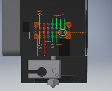
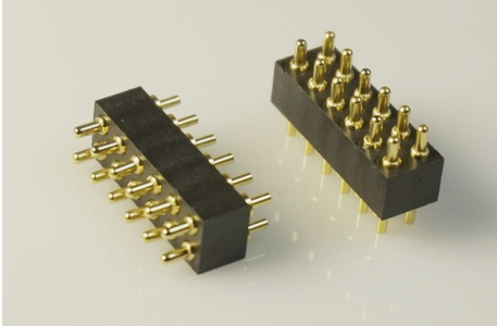
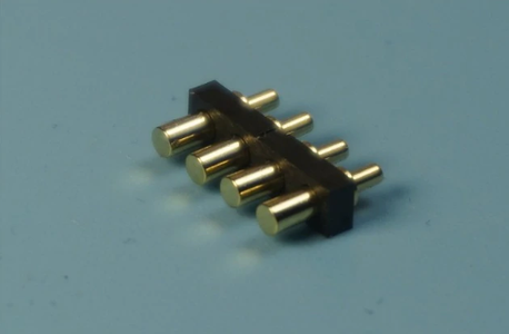
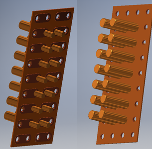
I have researched several solutions of quick connector types and choose pogo pins / spring loaded pins as the solution for my tool changing mechanism. The general idea is quiete simple. I’ll keep the current design of most parts. Except — obviously — the parts that have to be changed for the tool changer mechanics. Also I might use a CNC milled aluminium x-axis-carrier (instead of 2020 extursion) in the future.
First of all: I’ll need 12 wires for each tool head — because the bed leveling sensor is attached to the x-carriage. These wires are needed for:
- VCC & GND for the heater cartridge (30W @ 24V = 1.25 Amps)
- VCC & GND for the coldend cooling fan (< 0.2 Amps)
- VCC & GND for the part cooling fan (< 0.2 Amps)
- 4 phases for the stepper motor (<1.0 Amps per phase)
- 2 wires for the thermistor (<< 0.2 Amps)
The pogo pins / spring loaded pins I ordere have a current rating of 1A — so I’d need 4 (2xVCC & 2xGND) pins for the heater cartridge. I’ll also use the VCC-line of the heater cartridge for the fans (total current on these pins < 1.65 Amps).
In total I’d need at least 12 pins to make a suitable connector. In practice I think I’d use a 2.54mm pitch PCB with a size of 4×9 holes (see render). This would give me the possibilty to have up to 14 pogo pins + space for mounting it using M1.6 screws. The PCB would have a size of 10.2×22.9 mm. I hope to fit it «within» the air gap between the 2 aluminium plates on the x-carriage. I hope a similar solution will work with the E3D tool head (at least with a CAN-BUS board).
But there are some inherent problems with this apporach:
- Disconnetcting and connecting a stepper driver while it’s under power will fry the driver (if not immediatly at least over time),
- Connection problems — especially on the heater cartridge and thermistor pins may lead to undesirable «thermal runaway protection» triggers,
- There would be no way of monitoring the temperature, driving the coldend cooling fan and setting standy temperature while the tool head is in the tool dock (aka not attached to the x-carriage).
More DIY solutions for the meantime would be:
For #1: Using gcode to shut of the power to the driver with (i.e.) M18 E0. After sending this code it is safe to disconnect the stepper driver even while the board is powered on.
Remaining issue #1: What happens if the pogo pin connection is not reliable and «contact issues» occure during print moves?…so this would be issue #2…
For #3: That would be solvable due to the RepRaps firmware feature set and modularity through the gcode-programming and an additional set of pogo pins in the tool dock (for heater & coldend cooling fan). While the tool moves from the x-carriage to the dock all sensors, heaters, stepper drivers are detached in firmware via gcode-commands. After the tool head is parked in the dock the tool head is associated with that go from the Duet to the pogo pins in the tool dock.
Step 6: X / Y Gantry Assembly
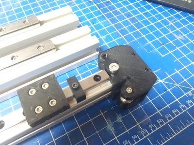


First mount your MGN9 rail centered on the 2020 aluminium extrusion and the MGN12 rails on the 3030 extrusion.
Position the 4 GT2-idlers on x-profile-mount and secure them using M3 screws and nuts. Slide the MGN9C carriage onto its rail. Afterwards attach the x-profile-mount to both sides of the using the MGN12H carriages, 3x M5 screws, 4 M3x Screws and 2x M5 T-Slot Nuts. Do not tighten the M5 screws all the way — they are tightened after installation to allow some air for tramming.
Slide the MGN12H carriages onto their rails (which are already mounted to the 3030 extrusions) and dry-fit everything onto your frame. If you have done everything correct and your frame is trammed neatly it should fit perfectly — otherwise slight persuasion might be necessary. DON’T USE BRUTE FORCE. This might bent your axis and you will need to buy new ones.
Fix the 3030 extrusion in place using 2x 3030 corner brackets and 2x T-Matik connectors. Slid the MGN12H carriages all the way to one end, back to the others and keep them parallel while doing so. After multiple repetitions everything should be mostly aligned.
Now you can finally tighten the 3x M5 screws on the x-profile-mount. Slide the x-axis back an forth one more time to see if everything runs smoothly. If not: loosen the M5 screws on the x-profile mount an try again.
After this you can install the mount for the belt idlers on the frame, install the belt, allign the pulleys and tension everything.
Congratulations. Your x/y-gantry is complete.
Step 1: Partslist — BOM
Hardware
- (number & length see excel)
- 2x Hiwin MGN12 rail (length see excel)
- 2x Hiwin MGN12H carriages
- 1x Hiwin MGN9 rail (length see excel)
- 1x Hiwin MGN9c carriage
- 50x T-Slot Nut, Slot 8, M3
- 4x LMK12LUU
- 2x GT2 Idler, 16 Tooth, Bore 3mm, without teeth
- 6x GT2 Idler, 16 Tooth, Bore 3mm, wit teeth
- 2x GT2 drive wheels, 16 Tooth, Bore 5mm (for Nema 17)
- GT2 Belt
- 2x bearing 6700 2RS (for top spindle mount)
- Coupling 5mm to 10mm (for spindle)
- 5x Nema 17 (body lenght <40mm)
- Build Plate, t>8mm (lenght see excel)
- IEC connector with fuse
- silicone damper or spring for bed
- drag chain for z-axis / heated bed (20 mm width)
- drag chain for x/y-gantry
- MPX 6 Pin connector (1 set male+female for each tool head)
- XT30 connector (1 set male+female for each tool head)
Electronics
- PTFE Tube
- Meanwell HLG-240h-24A
- capton tape or thermal adhesive (to mount the thermal fuse to the silicone heater OR in a groove on the bed)
- Silicone Heater (110V/240V, number & lenght see excel)
- Surface for built plate
- Wire Wrap for cables
Attachments
-
Bed_Bracket_15_1.0.stl
DownloadView in 3D - CoreBot.xlsxDownload
- CoreBot.rarDownload
-
Z_Axis_Bearing_Holder_LMK12LUU_Right.stl
DownloadView in 3D -
Z_Axis_Bearing_Holder_LMK12LUU_Left.stl
DownloadView in 3D -
Z_Nut_Tramming_Spacer.stl
DownloadView in 3D -
Z_Nut_mount_drylin.stl
DownloadView in 3D
Полярные 3D-принтеры
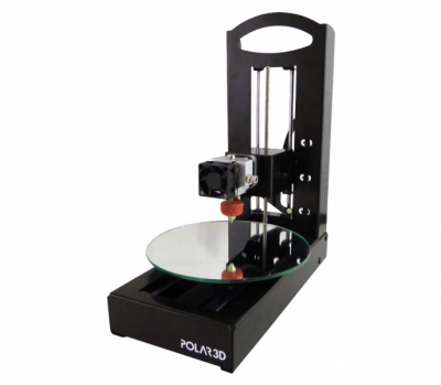
Достаточно новая, но интересная кинематическая полярная схема представлена на рынке одноименной компанией Polar. Как следует из названия, в печати используется полярная система координат — вместо привычных XYZ, позиционирование экструдера задается радиусом и углом.
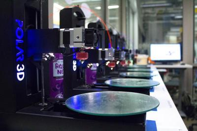
Платформа таких 3D-принтеров имеет круглую форму, вращается по кругу и двигается целиком по одной горизонтальной оси, при этом экструдер движется только вверх и вниз. Представьте себе виниловый проигрыватель – печатающая головка принтера работает по принципу иглы звукоснимателя, движущейся по пластинке. С той лишь разницей, что тут “пластинка” не только вращается, а “игла” наоборот ограничена в перемещениях.
Анализ роботизированных кинематических схем
Преимущества 3D-принтеров с роботизированным манипулятором очевидны – такой принтер не ограничен объемом рабочей камеры, которой у него нет – при той же области печати, само устройство занимает намного меньше места.

Экструдер может перемещаться не только послойно, как в настольных принтерах, но и по сложным траекториям в трех измерениях, и под разными углами, что облегчает процесс создания сложных конструкций. Несомненный плюс также то, что обычно это универсальные конструкции, при замене экструдера на другие блоки выполняющие множество задач.
По точности печати манипуляторы не составят конкуренции картезианским 3D-принтерам, но, благодаря своей универсальности и крупным размерам, промышленные роботы активно используются в 3D-печати в промышленных условиях, где почти незаменимы.
Миниатюрные настольные роботы хороши в первую очередь как наглядное пособие, а также объект хобби или инструмент для него.
Step 3: Frame Assembly
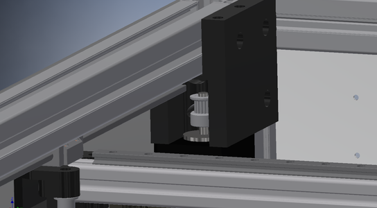
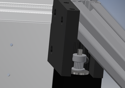
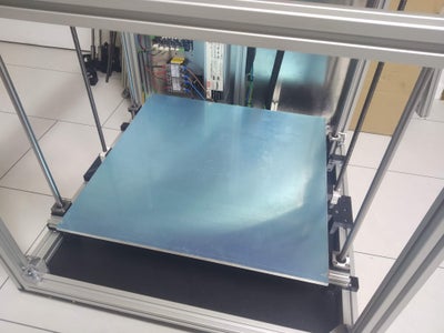
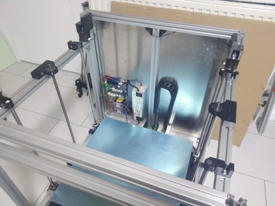
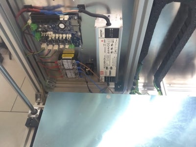
The frame assembly is pretty straight forwards — you don’t have to consider much. Just use the correct corner brackets in the right position.
There are two things you have to consider when assembling the frame:
- Mount the MGN12 rails to the 3030 y-extrusion before you put it into the frame. This will make your life easier. The MGN12 rail should have a distance of 10mm (x/y-idler) from one end, and 42mm (x/y-motor) from the other end.
- To mount the x/y-motor-mounts and Nema17 steppers correctly do the assembly in the follwoing order.
- Before mounting the top 3030 y-extrusion, mount the x/y-motor mount to the 3030 z-extrusion using 4x M5x10mm screws and t-slot nuts.
- Mount the Nema17 Motor (motor length < 40mm) to the x/y-motor mount and put the drive wheel (16 tooth) on the shaft. Mind the correct orientation (see pictures).
- At last but the top 3030 y-extrusion with the attached MGN12 rails into the frame.
SCARA
SCARA (Selective Compliance Articulated Robot Arm) — кинематика основанная на перемещении рабочего блока в горизонтальной плоскости за счет вращения в сочленениях рычажного механизма.
Построенные на данной схеме устройства отличаются очень высокой точностью и повторяемостью, намного выше чем у традиционных роботов-манипуляторов, низким уровнем шума и вибрации, компактностью. Если говорить о картезианских и SCARA-роботах сравнимых размеров и массы, то скара как правило не только точнее, но и быстрее.
В то же время, такие устройства дороги, имеют ограничения жесткости по осям XY, меньшую область работы и свободу движений.
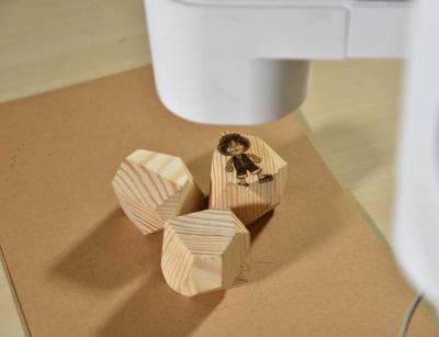
Примером такой кинематики может быть роборука Dobot M1. Это компактный настольный робот, совмещает в себе функции 3D-принтера и манипулятора. Действия программируются через установленное на компьютере ПО или мобильное приложение. Имеет сменные головки для печати, гравировки, пайки и сборки.
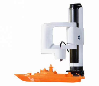
Пример работы:
Плюсы и минусы полярной механики
Полярные 3D-принтеры позволяют создавать крупные объекты, при этом экономя средства за счет высокой энергоэффективности. Они пока имеют низкую точность, но в долгосрочной перспективе, возможно, производитель сможет решить эту проблему.
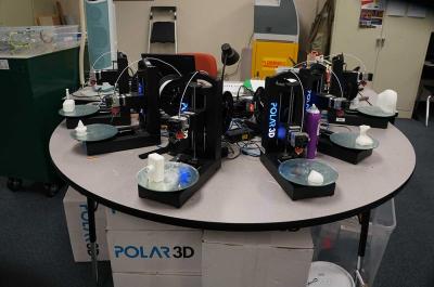
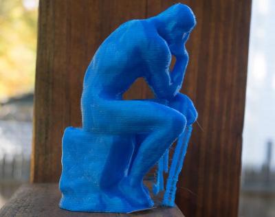
К таким 3D-принтерам относится модель Polar 3D. В данном 3D-принтере подогрев печатной платформы отсутствует, что затрудняет использование ABS. Имеет скромные габариты, хорошую производительность, но низкую точность, по сравнению с дельта-принтерами и моделями с декартовой системой координат. Производитель рекомендует приобретать модель для образовательных целей.
Пример печати:
Виды кинематики 3D-принтеров
Каждый 3D-принтер имеет собственную кинематическую схему, согласно которой приводятся в движение механические части устройства: платформы и экструдеры. Ниже мы рассмотрим четыре типа FDM 3D-принтера: картезианский, дельта, полярный и роботизированный манипулятор.
На рынке 3D-принтеров FFF / FDM самыми распространенными являются приборы с картезианской кинематикой. Основанная на декартовой системе координат, эта технология работает на основе трех осей – X, Y, Z. По одной или нескольким из них осуществляется движение механических частей прибора, т.е., заданные по осям координаты реализуют схему перемещения и положения печатающей головки относительно платформы.
Количество вариантов перемещения печатной головы и платформы ограничено:
-
Платформа передвигается по одной из горизонтальных осей — X или Y, экструдер движется по другой и в высоту.
-
Платформа перемещается по высоте, по оси Z, а экструдер передвигается по двум плоскостям, вперед-назад и влево-вправо.
-
Платформа движется по одной из осей и в высоту, экструдер — по другой оси.
-
Платформа неподвижна, экструдер передвигается по всем трем осям.
-
Платформа движется по осям XY, экструдер перемещается по высоте.
Вторая схема является самой распространенной — когда платформа для печати перемещается по оси Z (вверх и вниз), а экструдер работает в двух измерениях, по плоскостям XY.
Step 2: Component Choice and Failed Attempts

Linear Motion Components
X-Y-Movement:
I opted to use linear rails from Hiwin with a rail «width» of 12mm for the y- and 9mm for the x-axis. You are free to order them from china (approx. 80€). If you want the best experience choose geniune HIWIN-rails (which I recommend — QC in china is not that great, approx 700€).
Z-Movement:
The z-Axis consists 2 10mm lead screws and 4 12mm smooth rods to keep everything in place. I found that at the lenght of the spindels, which is needed for a 500mm z-movement, you need to constraint the spindle on the top AND bottom to keep distortion / ghosting-artifacts low. This will make tramming the z-axis a pain in the a***e but at the same time will strongly improve print quality.
Tool-Head
I tried different tool heads, mounting orientations and so on to find the «best» one. At first I tried an E3D V6 with bowden extruder. This did not work out at all. Due to the large travel distances the bowden tube flexed to much, causing to much friction in the tube and at last jamms. I tried to solve this problem with different solutions, but none worked (mounting the extruder on the back of the frame, on top of the frame in the center of the bed, using Capricorn and standard PTFE, using a filament oiler, re-assembling the hotend multiple times….).
After this I zip-tied my E3D Titan directly to the x-carriage. This immideatly solved all my jamming problems. Obviously this was no long term solution, so I designed and tested muldtiple hotend / extruder mounts. In the beginning I planned to use the E3D Titan Aero. A compact Extruder+Hotend-Solution which should be optimal! Which is kind of true — it works perfectly as planned, but there was room for improvement. I tried mounting the E3D Titan Aero in different orientations to reduce the overall footprint while keeping a powerfull fan attached to it for part cooling. The problem with this solution is the bulkiness of the assembly.
So I tried a different solution using an E3D V6 hotend with threaded heatsink and an E3D Titan Extruder. In the attached picture you can clearly see that the footprint of the tool head assembly is reduced by a large amount (yes, the comparison is not quite fair — the V6 version uses a smaller part cooling fan…but never the less…).
Not only the over all difference in footprint size is a nice feature of the V6 tool head. Due to the position of the extruder stepper motor on top of the x-carriage the center of gravity (COG) is much closer to the carriage itself reducing the torsional moment induced in the x-axis (see picture). This is true for the vertical offset (in z-direction of the printers frame) as well. The vertical offset of the Titan Aero V2 and Titan Aero V2.1 tool head is 32mm / 35mm. On the V6 tool head this offset can be reduced to 3mm due to the stepper motor / extruder and Hotend / fan «balancing» each other out.
The V6 currently uses a 40x40x10mm axial fan for hotend, and 40x40x10mm radial fan for part cooling. The overall size could be reduced further by using a 30x30x10mm fan for hotend cooling. Additionally the geometry of the fan duct for part cooling is not completely optimised.
Attachments
-
UBG_V6_Direct.stp
DownloadView in 3D -
UBG_TitanAero_V2.1.stp
DownloadView in 3D -
UBG_TitanAero_V2.stp
DownloadView in 3D
3D-принтеры с роботизированными манипуляторами
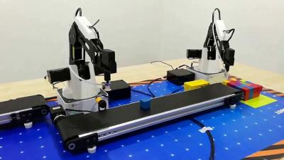
Представляют собой конструкцию с механическим программируемым манипулятором-захватом заменяемым экструдером. Если речь о крупных промышленных экземплярах (а бывают и более компактные), то, помимо функций манипулятора и 3D-принтера, такой робот может производить сварочные работы, фрезерование, покраску и другие операции.
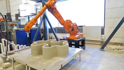
Хотя механика 3Д-печати с робо-рукой в основном применяется в промышленности, существуют модели для индивидуального использования, с широким набором функций.
Роборука Dobot Magician Educational обладает множеством функций.Может рисовать, писать, захватывать и перемещать предметы, выполнять лазерную гравировку и т.д.
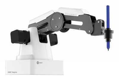
Пример работы:
Step 5: Tool Head Assembly
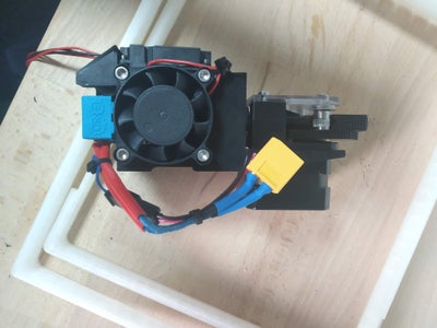
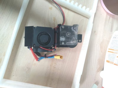

To assemble the tool head you can mostly use the greate guides by E3D:
To get everything aligned and assembled properly you have to do the assembly in the following order:
- Put 2 M3 Hex nuts in the slots on top of the printed part. The access to these holes will be blocked by the extruder stepper motor after assembly.
- Assemble the E3D V6 with threaded heatsink.
- Mount the E3D V6 Inside the hotend mount and Insert a short piece of PTFE.
- Assemble the E3D Titan (Bowden Version). There is only one tricky part: Getting the bowden coupling to slide into the E3D Titan’s housing.
- Attach the fans and route the wires using zip ties.
Step 8: Filament Runout Sensor & Spool Mount
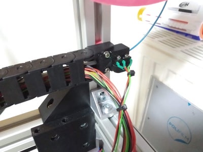
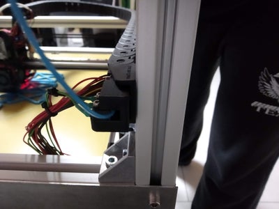
Update from 13th Jan. 2019
Filament Runout Sensor
I opted to add an (optional) Filament runout sensor. It is really annoying to have a long print «fail» because no material is left. Espacially with a large print size.
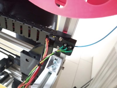
As a «sensor» I used a standard micro switch which only sense is filament is loaded or not. I did not want to implement a version of filament sensor which does not work realiably with differen kinds / colors of materials (Josef?).
As you might have guessed from the pictures I use a «reverse bowden» setup. The tool heads are direct drive but the filament is guided through the drag chain throug a 2/4mm PTFE tube (3/4mm might be better to reduce friction — the filament path in the drag chain does not have to be constraint at all). The PTFE tube directly attaches to the E3D Titan on one side and to the Filament runout sensor on the other side.
How to wire and setup a filament sensor for the Duet is described here:
Spool Mount / Rack
I included the parts for my spool mount / rack solution. It’s really simple. I just attached 2 spare pieces of 3030 extrusion to the printers top using 6030 (printed) and 3030 (bought) corner brackets. The length of the 3030 extrusion depends on the max spool diameter you want to use. To hold the spools I used a 12mm rod I had laying around.
In the beginning I thought I’d need some bearings (espacially for bigger 2.3kg spools. But until now everything works fine — even with the «hungry» 0.8mm Nozzle.
Attachments
-
CornerBracket_60mm.stl
DownloadView in 3D -
Spool_Rod_Mount.stl
DownloadView in 3D -
Coupling_Mount.stl
DownloadView in 3D
Introduction: CoreBot — CoreXY 3D Printer
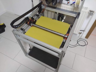


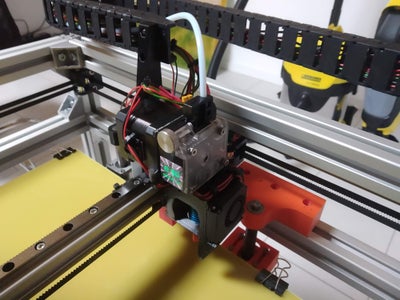
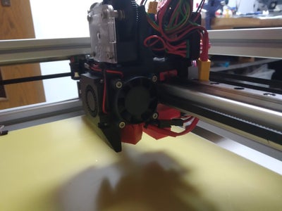 By MacNiteNiTecFollow
More by the author:
About: Maker, Engineer
More About MacNite »
I wanted to built a really reliable printer which is ready for the E3D tool changing mechanism, when it is finally realeased. At this stage this is only a big CoreXY machine because the E3D tool changer is not released yet. I also have doubts that the clamping / tool changing mechanism can bring up enough force to hold a direct drive extruder with a full sized Nema 17 stepper reliable. On my request E3D told me that a direct drive tool head should work. This has to be tested.
At first I planned to built a Hypercube / Hypercube Evolution but soon found I that the design was not stiff enough for the build area I was aiming for.
So I started optimising all parts and changed all linear guides to linear rails from Hiwin (MGN9 and MGN12). I also tried rails and bearings from IGUS but they did not work out for me (to much play). While doing so I also added an «electronics compartment» on the back using 3060 aluminium extrusion.
The printer features a built area of roughly 500x500x500mm. The y-axis is optimised to allow space for the tool changing mechanism. I included an Excel Sheet so you may calculate the requiered length, if you aim for a smaller or bigger version.
I opted to use a direct drive system, in the very first iteration (which was more like a Hypercube), I tried to use a bowden setup which did not work out at all. I got clogs all the time and re-assembled the hotend multiple times because I thought it was heat creap or a gap between the nozzel & heatbreak. But after zip-tying my E3D titan to the x-carriage everything went fine. Obviously the Hypercube is not suited to mount a heavy extruder onto the x-carriage on a printer this size.
Attachments
-
ZBG_Drucker_V2.stl
DownloadView in 3D -
ZBG_Drucker_V2.stp
DownloadView in 3D - SourceFiles_Inventor.rarDownload
Разновидности картезианской кинематики CoreXY и H-Bot
Данные кинематические схемы часто встречаются в коммерческих сферах. Отличаются оригинальными методами позиционирования экструдера. В обоих кинематиках платформа передвигается вверх-вниз.
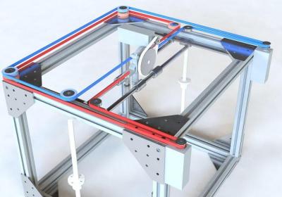
CoreXY имеет два закрепленных на раме двигателя, которые приводят в движение два ремня для перемещения каретки экструдера по осям XY.
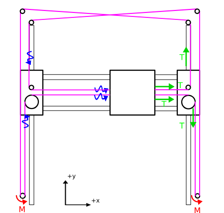
Кинематика H-Bot для 3D-принтера основана на похожей механике, но с другим ременным приводом. В данном случае ремень один и натянут по форме, напоминающей обведенную по контуру букву H (аш), за что схема и получила название аш-бот.

При работе обоих двигателей в одну сторону, каретка движется по оси X, в разные стороны — по оси Y. Когда один из двигателей остается неподвижным, каретка перемещается по диагонали.
Одним из примеров таких 3D-принтеров, может служить Designer X PRO. Эта модель отличается высокой скоростью, так как благодаря наличию функции JetSwitch, печать 2мя материалами стала еще быстрее (до 5 секунд в обычном режиме и 250 мс в черновом режиме). А заново спроектированная печатающая головка с точностью до 1 мкм, рамная конструкция, точная механика и аппаратная платформа нового поколения позволит вам напечатать модели высокого качества, сравнимые с промышленными изделиями. Обладает функцией двухматериальной печати. ПО полностью контролирует процесс, что минимизирует ошибки и увеличивает производительность 3D-принтера.
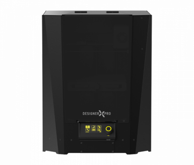
Пример печати:
Заключение
Выбирая устройство перед покупкой, прежде всего, определитесь с целью — зачем вам нужен 3D-принтер? Коммерция, работа или развлечение? Универсальность FFF / FDM 3D-принтеров в том, что они подходят для разных применений
Не важно, хотите ли вы изучить 3D-печать и приобрести новое хобби, воплотить в жизнь творческие фантазии или открыть бизнес — для реализации каждой из этих целей найдется подходящий аппарат, надо лишь выбрать. . Приобрести подходящий аппарат и расходные материалы можно в https://top3dshop.ru — розничном подразделении Top 3D Group, ведущего интегратора аддитивного оборудования в России
А также на сайте: https://top3dshop.com, если вы проживаете не в странах СНГ.
Приобрести подходящий аппарат и расходные материалы можно в https://top3dshop.ru — розничном подразделении Top 3D Group, ведущего интегратора аддитивного оборудования в России. А также на сайте: https://top3dshop.com, если вы проживаете не в странах СНГ.
Список используемых источников:
-
What are the advantages of the FDM technology? – Professional 3D Printers // : dddrop.com – Электрон. дан. – dddrop.com – Режим доступа: https://www.dddrop.com/fdm-technology/ (дата обращения: 03.08.2019).
-
Application of FDM three-dimensional printing technology in the digital manufacture of custom edentulous mandible trays // : Scientific Reports – Электрон. дан. – nature.com – Режим доступа: https://www.nature.com/articles/srep19207 (дата обращения: 03.08.2019).
-
Reconstruction and Development of a 3D Printer Using FDM Technology // : Procedia Engineering – Электрон. дан. – sciencedirect.com – Режим доступа: https://www.sciencedirect.com/science/article/pii/S1877705816311651 (дата обращения: 03.08.2019).
-
Catalog // : 3D Printers – Электрон. дан. – top3dshop.com – Режим доступа: https://top3dshop.com/3d-printers/ (дата обращения: 03.08.2019).
-
Каталог // : 3D Printers – Электрон. дан. – top3dshop.ru – Режим доступа: https://top3dshop.ru/kupit-3d-printer/ (дата обращения: 03.08.2019).
