Начало работы с esp8266 nodemcu v3 lua с wifi
Содержание:
- gpio.serout()
- Обновление прошивки ESP8266
- Общие сведения
- Cloud Builder
- Introduction: NodeMCU ESP8266: Details and Pinout
- Настройка ESP8266
- node.info()
- gpio.pulse:adjust
- Example code
- node.random()
- gpio.pulse.build
- Step 3: But, What Is the Correct Pinout for Me to Use for My ESP32?
- ESP8266 12-E Chip Pinout
- Требования к питанию
- Step 11: Boot
- Tools
- Настройка IDE
- Платформы разработки для ESP8266
gpio.serout()
Serialize output based on a sequence of delay-times in µs. After each delay, the pin is toggled. After the last cycle and last delay the pin is not toggled.
The function works in two modes:
* synchronous — for sub-50 µs resolution, restricted to max. overall duration,
* asynchrounous — synchronous operation with less granularity but virtually unrestricted duration.
Whether the asynchronous mode is chosen is defined by presence of the parameter. If present and is of function type the function goes asynchronous and the callback function is invoked when sequence finishes. If the parameter is numeric the function still goes asynchronous but no callback is invoked when done.
For the asynchronous version, the minimum delay time should not be shorter than 50 μs and maximum delay time is 0x7fffff μs (~8.3 seconds).
In this mode the function does not block the stack and returns immediately before the output sequence is finalized. HW timer mode is used to change the states. As there is only a single hardware timer, there
are restrictions on which modules can be used at the same time. An error will be raised if the timer is already in use.
Note that the synchronous variant (no or nil parameter) function blocks the stack and as such any use of it must adhere to the SDK guidelines (also explained ). Failure to do so may lead to WiFi issues or outright to crashes/reboots. In short it means that the sum of all delay times multiplied by the number of cycles should not exceed 15 ms.
Parameters
- pin to use, IO index
- level to start on, either or
- an array of delay times in µs between each toggle of the gpio pin.
- an optional number of times to run through the sequence. (default is 1)
- an optional callback function or number, if present the function returns immediately and goes asynchronous.
Обновление прошивки ESP8266
Модуль ESP8266 замечателен тем, что не требует специального программатора — обновление прошивки производится на том же железе, на котором вы подключаете модуль ESP8266 к компьютеру, т.е. тоже через USB-TTL конвертер (ну или Arduino или RPi). Для обновление прошивки на модуле ESP8266 проделайте следующее:
для Win систем подойдет XTCOM UTIL (удобно работать, если прошивка состоит из одного файла), мультиплатформенный esptool (требуется python, нужно указывать параметры в командной строке), FLASH DOWNLOAD TOOL (много настроек, удобно прошивать прошивки, состоящие из нескольких файлов, позволяет «собрать» прошивку в один файл из нескольких). Также вы найдете и другие программы для прошивки ESP8266 — попробуйте разные и пользуйтесь той, которая вам больше понравится.
3. Отключите от последовательного порта вашу терминальную программу
4. Отключите CH_PD от питания, подключите GPIO0 модуля к GND, подключите обратно CH_PD модуля.
5. Запускайте программу для прошивки модуля и загружайте новую прошивку в модуль ESP8266.
Загрузка прошивки в модуль обычно осуществляется на скорости 115200, но режим прошивки модуля поддерживает автоопределение скорости и прошивка может быть осуществлена на скорости от 9600 и выше. Максимальная скорость зависит от многих факторов (вашего USB-TTL конвертера, длины проводов и прочего) и может быть определена экспериментально на конфигурации именно вашего оборудования.
Все последние версии прошивок загружаются с нулевого адреса (0x00000).
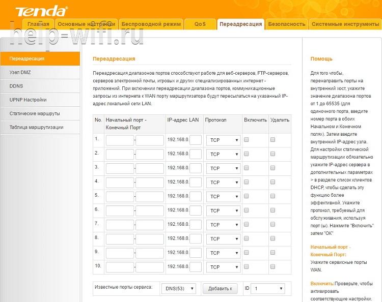
В статье Обновление прошивки ESP8266 подробно описана загрузки прошивки в модуль с помощью программы XTCOM_UTIL.
Использованная литература
Общие сведения
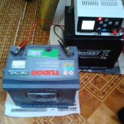
Второй вариант контроллера выполнен на распространенном («народном») Wi-Fi модуле типа NodeMCU, в основе которого достаточно мощная система-на-кристалле (СнК) Espressif ESP8266. Такое решение позволит реализовать в нашем контроллере подсветки дополнительные функции, присущие устройствам Интернета вещей (Рисунок 10). На сегодняшний день существует множество разновидностей этих Wi-Fi модулей, отличающихся форм-фактором, количеством линий ввода/вывода общего назначения, наличием интерфейса для отладки и программирования. Подобное разнообразие обусловлено высокой популярностью Wi-Fi модулей среди радиолюбителей и конструкторов, а также полной поддержкой ядра ESP8266 в интегрированной среде разработки Arduino IDE. Другими словами, это миниатюрная Arduino-плата с Wi-Fi интерфейсом, с помощью которой можно создавать устройства Интернета вещей (IoT) с достаточно богатым функционалом.
 |
|
| Рисунок 10. | Контроллер управления подсветкой рабочей зоны на кухне (версия на NodeMCU) поддерживает IoT функции. |
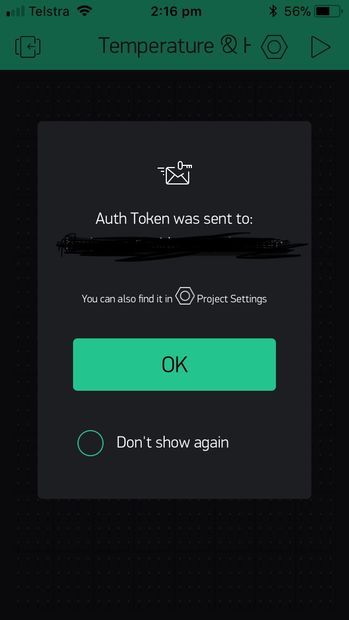
Идея внедрить IoT функции в контроллер подсветки родилась после того, как я оценил возможности облачного сервиса и мобильного приложения myDevices Сayenne для разработки IoT устройств на Raspberry Pi и Arduino . Рекомендую ознакомиться с опубликованными на нашем портале обзорами, чтобы понять принцип построения и работы системы.
 |
|
 |
|
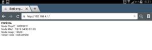
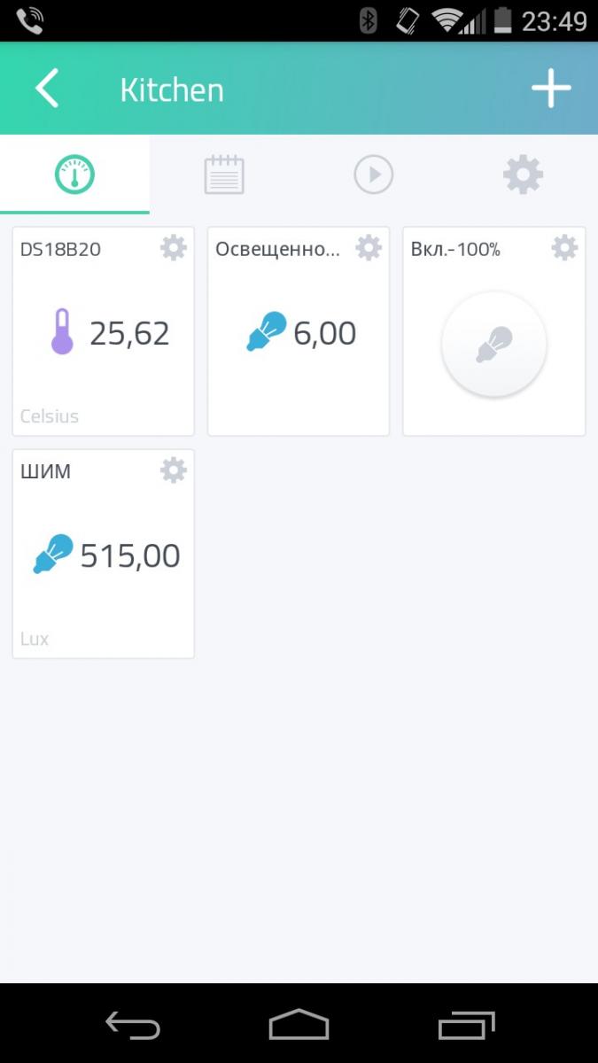
| Рисунок 11. | Приборная панель Cayenne для контроллера управления подсветкой на кухне: а) в браузере; б) в приложении. |
Теперь, учитывая, что контроллер автоматического управления подсветкой поддерживает Интернет подключение (в частности, к серверу Cayenne), мы можем реализовать дополнительные полезные функции удаленного контроля и управления. На данный момент на приборной панели Cayenne я могу наблюдать за уровнем освещенности и его изменением, режимом работы ШИМ контроллера, температурой в помещении, а также могу из приложения на смартфоне перевести контроллер в ручной режим работы и включить подсветку на максимальную яркость (Рисунок 11). Все данные, поступающие на сервер Cayenne, сохраняются, и в дальнейшем я могу посмотреть (и скачать) статистику изменения данных по различным периодам времени, а также настроить условия оповещения на мобильный телефон или электронную почту (Рисунок 12). Таким образом, данный контроллер, помимо управления подсветкой рабочей зоны на кухне, может выполнять дополнительные функции автоматизации и является в некотором смысле удаленным датчиком (сенсорным узлом).
 |
|
| Рисунок 12. | Один из вариантов графического отображения в Cayenne статистики по датчику температуры на кухне. |
Дальше мы подробно рассмотрим устройство и принцип работы этого варианта контроллера.
Cloud Builder
- one for NodeMCU with floating support
- one for NodeMCU without floating support i.e. an integer-only binary
We recommend using the floating point build, even though the integer variant uses less RAM for storing variables, as there is little runtime difference between the two variants. Furthermore, the floating point variant handles non-integer values properly and this greatly simplifies numeric calculations.
For everything else the cloud builder GUI is self-explanatory. Hence, no need for further explanations here.
For LFS
- Expand the «LFS options» panel
- Select an LFS size, 64KB is likely going to be large enough
- Select other options and build
Note that this service is not maintained by the NodeMCU team. It’s run by a NodeMCU team member as an individual, though.
Introduction: NodeMCU ESP8266: Details and Pinout
By Fernando KoyanagiVisit my Site!Follow
More by the author:
About: Do you like technology? Follow my channel on Youtube and my Blog. In them I put videos every week of microcontrollers, arduinos, networks, among other subjects.
More About Fernando Koyanagi »
Today, we will talk about ESP8266 pinning, or in other words, NodeMCU. Personally, I really like this component, as it already comes with USB input. But it is important to explain that the NodeMCU is formed by an ESP12E, which still has an ESP8266EX inside it. Thus, we’ll learn the correct pin identification by doing the following: looking at the NodeMCU datasheet, knowing which of these pins work with digitalWrite, digitalRead, analogWrite, and analogRead, and understanding the boot more thoroughly.
As I program more with Arduino IDE, I practically see the NodeMCU as an Arduino. However, I must emphasize these devices have differences, especially concerning the pinning. If you watched the ESP32 video entitled “Internal Details and Pinout,” you’ve learned there are pins that can’t be used, or that are reserved for certain things. So I want to do something useful here related to this, but this time with ESP8266.
Настройка ESP8266
Итак, ESP8266 модуль к USB порту мы подключили (через USB-TTL или Arduino) теперь нужно убедится, что драйвера к вашим USB-TTL или Arduino встали корректно и в системе появился новый виртуальный последовательный порт. Вам понадобится программа — терминал последовательного порта. Можете использовать любую на ваш вкус, но она должна удовлетворять следующему требованию: каждая команда, которую вы отправляете с компьютера в последовательный порт должна завершаться символами CR+LF.
Ваш покорный слуга является автором open-source программы ESPlorer, получившей международное признание. ESPlorer позволит вам не вводить AT команды вручную и легко работать с lua скриптами под NodeMCU (об этом в другой раз) и вы вполне можете использовать ее и как обычный терминал. Обсуждение ESPlorer на нашем форуме и на esp826.com
С подключением к последовательному порту придется немного поколдовать: в связи с разнообразием прошивок для ESP8266, подключение может осуществляться на разных скоростях. Нужную скорость можно определить путем простого перебора трех вариантов: 9600, 57600 и 115200. Как осуществить перебор? Подключаетесь в терминальной программе к вашему виртуальному последовательному порту выставив следующие параметры: 9600 8N1, затем перезагружаете модуль, отключив CH_PD (chip enable) от питания (USB-TTL при этом остается подключенным к USB) и снова включаете (т.е. просто передергиваете CH_PD, почему не передергиваем питание — читаем , также можно кратковременно замкнуть RESET на землю для перезагрузки модуля) и наблюдаете данные в терминале. Во-первых, светодиоды на ESP8266 должны гореть как описано в начале статьи в разделе . Во-вторых, в терминале вы должны увидеть «мусор» из разных символов, оканчивающийся строкой «ready». Если «ready» мы не видим, то переподключаемся терминалом на другой скорости и снова перезагружаем модуль.
На одном из вариантов скорости «ready» вы все-таки увидите — поздравляем, ваш модуль готов к работе. Если нет, то добро пожаловать к нам на форум — мы постараемся помочь, но предварительно почитайте эту тему.
Немного подробнее о «мусоре». Дело в том, что при старте прошивки, UART модуля ESP8266 переключается на скорость передачи 74 880 (вот такие забавные эти китайцы) выдает в UART отладочную информацию, затем переключает скорость порта на 115200 (ну или на 9600 или 57600 в зависимости от версии прошивки), так вот эта отладочная информация и видится нам как мусор, т.к. мы подключаемся к модулю на другой скорости. Можете подключится к ESP8266 на скорости 74 880 (ESPlorer поддерживает эту скорость) и вы эту отладочную информацию увидите, будет что-то вроде этого:
wdt reset
load 0x40100000, len 25052, room 16
tail 12
chksum 0x0b
ho 0 tail 12 room 4
load 0x3ffe8000, len 3312, room 12
tail 4
chksum 0x53
load 0x3ffe8cf0, len 6576, room 4
tail 12
chksum 0x0d
csum 0x0d
|
1 |
wdt reset load0x40100000,len25052,room16 tail12 chksum0x0b hotail12room4 load0x3ffe8000,len3312,room12 tail4 chksum0x53 load0x3ffe8cf0,len6576,room4 tail12 chksum0x0d csum0x0d |
НО! не увидите «ready» и не сможете управлять модулем, пока не переподключитесь на ту скорость, на которой работает прошивка.
node.info()
Returns information about hardware, software version and build configuration.
Parameters
A designator for a group of properties. May be one of , , . It is currently optional; if omitted the legacy structure is returned. However, not providing any value is deprecated.
Returns
If a is given the return value will be a table containing the following elements:
- for =
- (number)
- (number)
- (number)
- (number) 0 = QIO, 1 = QOUT, 2 = DIO, 15 = DOUT.
- (number)
- for =
- (string)
- (string)
- (string) release name +additional commits e.g. «2.0.0-master_20170202 +403»
- (string) commit timestamp in an ordering format. e.g. «201908111200»
- (number)
- (number)
- (number)
- for =
- (boolean)
- (number) as defined at build time
- (string) comma separated list
- (string) or
Attention
Not providing a is deprecated and support for that will be removed in one of the next releases.
- for =
- (number)
- (number)
- (number)
- (number)
- (number)
- (number)
- (number)
- (number)
gpio.pulse:adjust
This adds (or subtracts) time that will get used in the / delay case. This is useful if you are trying to
synchronize a particular state to a particular time or external event.
Returns
- is the index of the currently active state. The first state is state 1. This is if the output operation is complete.
-
is the number of states that have been executed (including the current one). This allows monitoring of progress when there are
loops. - is the time (in microseconds) until the next state transition. This will be negative once the output operation is complete.
- is the value of the function at the instant when the was calculated.
Example code
Just as a very simple example code, we are going to use one of these mapping in the famous blink example. To avoid the need for external hardware, we are going to use the NodeMCU built in LED, which is connected to pin D0 of the board .
So, we are going to use the defined D0 constant to control the LED without the need to worry about the mapping to the actual ESP8266 GPIO pin.
void setup() {

  pinMode(D0, OUTPUT); //Declare Pin mode

}

void loop() {

  digitalWrite(D0, HIGH);   //Turn the LED on
  delay(1000);              //Wait 1 second
  digitalWrite(D0, LOW);    //Turn the LED off
  delay(1000);              //Wait 1 second

}
Note that we could also have used the LED_BUILTIN constant, which would map to the same exact result.
As an additional test, you can also try to print these constants to the serial port and confirm that the mappings are correct.
node.random()
This behaves like math.random except that it uses true random numbers derived from the ESP8266 hardware. It returns uniformly distributed
numbers in the required range. It also takes care to get large ranges correct.
It can be called in three ways. Without arguments in the floating point build of NodeMCU, it returns a random real number with uniform distribution in the interval [0,1).
When called with only one argument, an integer n, it returns an integer random number x such that 1 <= x <= n. For instance, you can simulate the result of a die with random(6).
Finally, random can be called with two integer arguments, l and u, to get a pseudo-random integer x such that l <= x <= u.
Parameters
- the number of distinct integer values that can be returned — in the (inclusive) range 1 ..
- the lower bound of the range
- the upper bound of the range
gpio.pulse.build
This builds the object from the supplied argument (a table as described below).
Parameter
this is view as an array of instructions. Each instruction is represented by a table as follows:
- All numeric keys are considered to be pin numbers. The values of each are the value to be set onto the respective GPIO line.
For example would set pin 1 to be high.
Note this that is the NodeMCU pin number and not the ESP8266 GPIO number. Multiple pins can be
set at the same time. Note that any valid GPIO pin can be used, including pin 0. - specifies the number of microseconds after setting the pin values to wait until moving to the next state. The actual delay may be longer than this value depending on whether interrupts are enabled at the end time. The maximum value is 64,000,000 — i.e. a bit more than a minute.
- and can be used to specify (along with ) that this time can be varied. If one time interval overruns, then the extra time will be deducted from a time period which has a or specified. The actual time can also be adjusted with the API below.
- and allow simple looping. When a state with and is completed, the next state is at (provided that has not decremented to zero). The count is implemented as an unsigned 32 bit integer — i.e. it has a range up to around 4,000,000,000. The first state is state 1. The is rather like a goto instruction as it specifies the next instruction to be executed.
Example
This will generate a square wave on pins 1 and 2, but they will be exactly out of phase. After 10 seconds, the sequence will end, with pin 2 being high.
Note that you must set the pins into output mode (either gpio.OUTPUT or gpio.OPENDRAIN) before starting the output sequence, otherwise
nothing will appear to happen.
Step 3: But, What Is the Correct Pinout for Me to Use for My ESP32?
ESP32 is not difficult. It’s so easy that we can say that there is no didactic concern in your environment. However, we need to be didactic, yes. If you want to program in Assembler, that is okay. But, engineering time is expensive. So, if everything that is a technology supplier gives you a tool that takes time to understand its workings, this can easily become a problem for you, because all this will increase the engineering time, while the product is becoming increasingly expensive. This explains my preference for easy things, those that can make our day to day easier, because time is important, especially in today’s busy world.
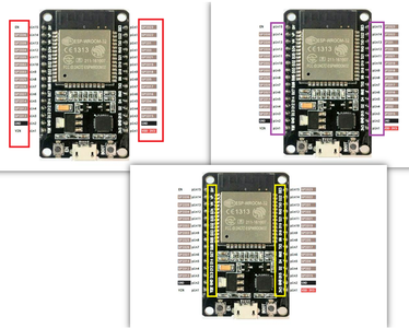
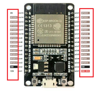
Returning to the ESP32, in a datasheet, as in the one above, we have the correct pin identification in the highlights. Often, the label on the chip doesn’t match the actual number of the pin, as we have three situations: the GPIO, the serial number, and also the code of the card itself.
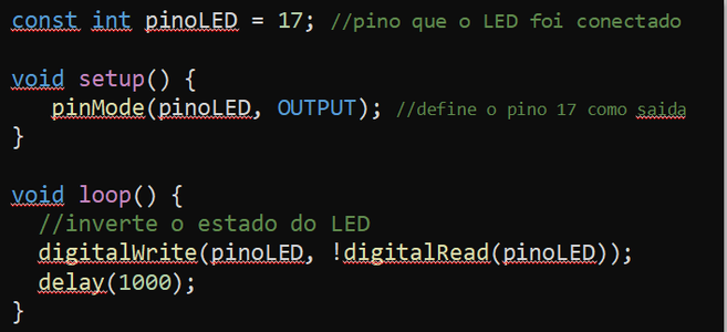
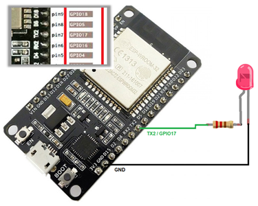
As shown in the example below, we have a connection of a LED in the ESP and the correct mode of configuration:
Notice that the label is TX2, but we must follow the correct identification, as highlighted in the previous image. Therefore, the correct identification of the pin will be 17. The image shows just how close the code should stay.
ESP8266 12-E Chip Pinout
The following figure illustrates the ESP8266 12-E chip pinout. Use this diagram if you’re using an ESP8266 bare chip in your projects.
Note: not all GPIOs are accessible in all development boards, but each specific GPIO works in the same way regardless of the development board you’re using. If you’re just getting started with the ESP8266, we recommend reading our guide: Getting Started with the ESP8266.
At the moment, there are a wide variety of development boards with the ESP8266 chip that differ in the number of accessible GPIOs, size, form factor, etc…
The most widely used ESP8266 boards are the ESP-01, ESP8266-12E NodeMCU Kit, and the Wemos D1 Mini. For a comparison of these board, you can read this guide: ESP8266 Wi-Fi Development Boards comparison.
Требования к питанию
Поскольку диапазон рабочего напряжения ESP8266 составляет от 3 В до 3,6 В, данная плата для поддержания постоянного напряжения на уровне 3,3 В поставляется с LDO стабилизатором напряжения. Он может надежно обеспечивать ток до 600 мА, чего должно быть более чем достаточно, поскольку ESP8266 во время радиочастотных передач потребляет до 80 мА. Выход стабилизатора также выводится на выводы на сторонах платы и обозначен как 3V3. Эти выводы можно использовать для подачи питания на внешние компоненты.
Требования к питанию
- Рабочее напряжение: от 2,5 до 3,6 В
- Встроенный стабилизатор: 3,3 В, 600 мА
- Рабочий ток: 80 мА
- Потребление в спящем режиме: 20 мкА
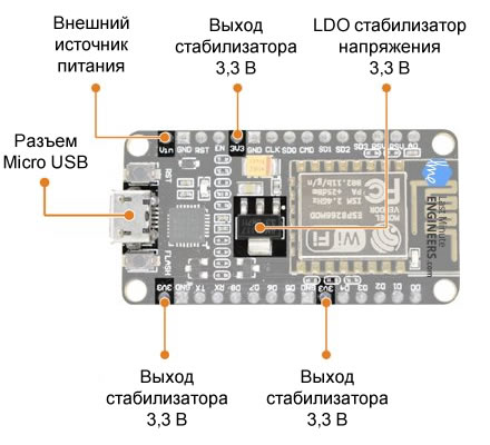 Рисунок 2 – Элементы питания ESP8266 NodeMCU
Питание к ESP8266 NodeMCU подается через встроенный USB-разъем MicroB. В качестве альтернативы, если у вас есть стабилизированный источник напряжения 5 В, можно использовать вывод VIN для непосредственного питания ESP8266 и его периферии.
Предупреждение
ESP8266 требует 3,3 В для питания и логические уровни 3,3 В для связи. Контакты GPIO не допускают напряжение 5 В! Если вы хотите соединить плату со схемами 5 В (или выше), то необходимо реализовать согласование логических уровней.
Step 11: Boot

On many development boards with embedded USB / Serial, esptool.py can automatically reset the board to boot mode.
ESP32 will enter the serial boot loader when the GPIO0 is kept low on the reset. Otherwise, it will run the program in flash.
GPIO0 has an internal pullup resistor, so if it is without a connection, it will go high.
Many boards use a button labeled «Flash» (or «BOOT» on some Espressif development boards) that leads the GPIO0 downward when pressed.
GPIO2 should also be left unconnected / floating.
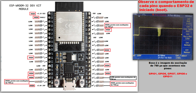
In the image above, you can see a test that I performed. I put the oscilloscope on all the pins of the ESP to see what happened when it was turned on. I discovered that when I get a pin, it generates oscillations of 750 microseconds, as shown in the highlighted area on the right side. What can we do about this? We have several options, like giving a delay with a circuit with a transistor, a door expander, for example. I point out that GPIO08 is reversed. The oscillation exits upwards and not downwards.
Another detail is that we have some pins that start in High, and others in Low. Therefore, this PINOUT is a reference to when the ESP32 turns on, especially when you are working with a load to trigger, for example, a triac, a relay, a contactor, or some power.
Tools
Transferring application code to ESP8266/8285 is an essential task, one that you’ll perform quite frequently. Hence, it does make sense to try a few different uploading tools until you find one you feel comfortable with. https://frightanic.com/iot/tools-ides-nodemcu/ lists almost a dozen classical uploaders — in addition to IDEs or IDE-like applications which of course transfer code as well.
The NodeMCU firmware team does not give any recommendations as for which uploader to use nor are there any «NodeMCU approved» tools. The below listed tools are just three, in no particular order, which seem popular and/or reasonably well maintained.
ESPlorer

Source: https://github.com/4refr0nt/ESPlorer
Supported platforms: macOS, Linux, Windows, anything that runs Java
nodemcu-uploader.py
Source: https://github.com/kmpm/nodemcu-uploader
Supported platforms: macOS, Linux, Windows, anything that runs Python
NodeMCU-Tool
Source: https://github.com/andidittrich/NodeMCU-Tool
Supported platforms: macOS, Linux Windows, anything that runs Node.js
Настройка IDE
ESPlorer написан на JAVA. Интерфейс приложения такой.
ESPlorer
С левой стороны код, настройки и подобное. С правой — окно мониторинга и команды управления девайсом. Открываем приложение, выбираем порт. Устанавливаем скорость, на которой будет происходить обмен (вероятнее всего, это 115 200), и нажимаем Open.
Установка скорости порта в ESPlorer
Для разминки можно запустить простой скрипт, который мигает встроенным светодиодом:
Если на нашей плате нет встроенного светодиода (или тебе уже вконец надоели примеры моргания светодиодом), то можно попробовать выполнить еще более простой скрипт, который выводит на экран строку:
После того как создашь файл формата .lua (допустим, test.lua), внесешь в него код и сохранишь на диск, можно будет загрузить его на устройство. Для этого необходимо открыть порт, если он не открыт (кнопка Open), и нажать кнопку Upload. Ее можно найти среди кнопок, которые расположены под кодом (слева).
Загрузив файл, выполним его, отправив команду
Команду можно ввести вручную в нижнее поле, расположенное справа под монитором. Особо ленивые, а точнее — рациональные программисты могут нажать кнопку Reload (крайний ряд кнопок справа). Появится список кнопок с загруженными на плату файлами .lua. Нажатие на кнопку с именем файла запустит файл на исполнение.
Если хочешь, чтобы файл запускался сразу после включения платы, то создай файл с именем AUTOEXEC.BA… тьфу, то есть init.lua.
Платформы разработки для ESP8266
Теперь перейдем к интересным вещам!
Существует множество платформ разработки, которые могут быть оснащены для программирования ESP8266. Вы можете использовать Espruino – JavaScript SDK и прошивка, эмулирующая Node.js, или использовать Mongoose OS – операционную систему для устройств IoT (рекомендуемая платформа от Espressif Systems и Google Cloud IoT), или использовать комплект разработки программного обеспечения (SDK), предоставляемый Espressif. или любую из платформ, перечисленных на .
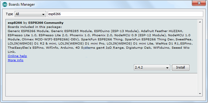
К счастью, крутое сообщество ESP8266 сделало выбор IDE на шаг вперед, создав дополнение к Arduino IDE. Если вы только начинаете программировать для ESP8266, мы рекомендуем начать с этой среды разработки, и ее мы опишем в данном руководстве.
Это дополнение ESP8266 для Arduino IDE основано на работе Ивана Грохоткова и остальной части сообщества ESP8266. Для получения дополнительной информации смотрите репозиторий GitHub ESP8266 Arduino.