Базовые принципы работы с gpio raspberry pi
Содержание:
- Способы взаимодействия с интерфейсом GPIO
- Become a more advanced programmer
- Configuration
- GPIO Zero documentation and resources
- Пины питания и заземления
- Sections of the dt-blob
- Overview
- General Purpose Input Output (GPIO) Pins
- Распиновка разъемов GPIO
- Распиновка DSI разъема дисплея
- Custom blocks
- Использование пинов и меры безопасности
- Source/values properties
- UARTs and Device Tree
- Controlling timings and resolutions
- Ground (gnd)
- Распиновка CSI разъема камеры
- Developing GPIO Zero
- Заключение
Способы взаимодействия с интерфейсом GPIO
Интерфейсная гребенка позволяет работать с собой несколькими путями:
- встроенными инструментами Linux (через интерпретатор bash и средства файловой системы);
- посредством языков программирования.
Управление на bash
Если использовать Raspbian, «баш» доступен по умолчанию. Пример отправки логического «1» на пин номер 25:
Чтение данных со входа номер 24:
Управление через Python
Питон — один из самых популярных языков разработки под Raspberry, и в нем создан богатый инструментарий. В последних дистрибутивах ОС Raspbian уже присутствует и сама среда Python, и необходимая для работы библиотека RPi.GPIO. Если же таковой нет, ее можно загрузить из репозитория:
Далее необходимо подгрузить этот модуль в программу:
Далее следует определиться с порядком нумерации — брать ли «физический» по номерам портов на микрокомпьютере, или использовать принцип обращения по номерам процессорных каналов (BCM):
Преимущество первого пути — универсальность: он будет работать с любой ревизией контроллера. BCM обращается непосредственно к каналам процессора на более низком уровне.
На следующем шаге выбирается режим работы портов input или output.
Сразу же можно определить начальное состояние выходов RPi3:
Команда на чтение информации со входа:
Запись значения на выход GPIO:
Пример работы
Рассмотрим пример взаимодействия RPi3 и простой схемы со светодиодом через написанную на Python программу.
Для начала понадобится «малинка» с установленным ПО и средой разработки, макетная плата, диод, кнопка и резисторы. Схема подключения приведена ниже:
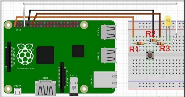
Здесь R1 имеет сопротивление 10 кОм, R2 — 1 кОм, а резистор R3 — 220 кОм.
Что обеспечивает подобная модель:
- без нажатия кнопки на входе пина возникает напряжение 3.3 В;
- при нажатии кнопки через нее и резистор R1 начнет подаваться ток 0.33 мА, а на входе схема обеспечит 0 В;
- при неверном подключении пинов по схеме потечет ток безопасных значений, предохраняя систему от повреждения.
Написанный на Python скрипт включения-выключения лампочки:
Для «моргания» диодом:
Включение лампочки с кнопки:
Пример управления выходами с клавиатуры:
Готовую программу следует сохранить в удобную папку и запустить командой Питона:
Python предоставляет широкое поле возможностей для программирования «Распберри» и позволяет реализовывать гораздо более сложные схемы. Кроме того, с платой можно взаимодействовать на практически любом распространенном языке — одном из семейства C, Perl, Erlang и другое. Существуют даже реализации проектов на Java и HTML5.
Become a more advanced programmer
As a beginner to programming, you usually start by writing procedural programs, in which the flow moves from top to bottom. Then you’ll probably add loops and create your own functions. Your next step might be to start using libraries which introduce new patterns that operate in a different manner to what you’ve written before, for example threaded callbacks (event-driven programming). You might move on to object-oriented programming, extending the functionality of classes provided by other libraries, and starting to write your own classes. Occasionally, you may make use of tools created with functional programming techniques.
Take control of the buttons in your life
It’s much the same with GPIO Zero: you can start using it very easily, and we’ve made it simple to progress along the learning curve towards more advanced programming techniques. For example, if you want to make a push button control an LED, the easiest way to do this is via procedural programming using a loop:
But another way to achieve the same thing is to use events:
You could even use a declarative approach, and set the LED’s behaviour in a single line:
You will find that using the procedural approach is a great start, but at some point you’ll hit a limit, and will have to try a different approach. The example above can be approach in several programming styles. However, if you’d like to control a wider range of devices or a more complex system, you need to carefully consider which style works best for what you want to achieve. Being able to choose the right programming style for a task is a skill in itself.
Configuration
By default, only UART0 is enabled. The following table summarises the assignment of the first two UARTs:
| Model | first PL011 (UART0) | mini UART |
|---|---|---|
| Raspberry Pi Zero | primary | secondary |
| Raspberry Pi Zero W | secondary (Bluetooth) | primary |
| Raspberry Pi 1 | primary | secondary |
| Raspberry Pi 2 | primary | secondary |
| Raspberry Pi 3 | secondary (Bluetooth) | primary |
| Raspberry Pi 4 | secondary (Bluetooth) | primary |
Note: the mini UART is disabled by default, whether it is designated primary or secondary UART.
Linux devices on Raspberry Pi OS:
| Linux device | Description |
|---|---|
| mini UART | |
| first PL011 (UART0) | |
| primary UART | |
| secondary UART |
Note: and are symbolic links which point to either or .
GPIO Zero documentation and resources
On the , we provide beginner recipes and advanced recipes, and we have added remote GPIO configuration including PC/Mac/Linux and Pi Zero OTG, and a section of GPIO recipes. There are also new sections on source/values, command-line tools, FAQs, Pi information and library development.
You’ll find plenty of cool projects using GPIO Zero in our learning resources. For example, you could check out the one that introduces physical computing with Python and get stuck in! We even provide a GPIO Zero cheat sheet you can download and print.
There are great GPIO Zero tutorials and projects in The MagPi magazine every month. Moreover, they also publish Simple Electronics with GPIO Zero, a book which collects a series of tutorials useful for building your knowledge of physical computing. And the best thing is, you can download it, and all magazine issues, for free!
Check out the API documentation and read more about what’s new in GPIO Zero on my blog. We have lots planned for the next release. Watch this space.
Пины питания и заземления
Контакты питания и заземления используются для питания внешних цепей. Все Raspberry Pi со стандартными контактами 40 GPIO будут иметь два контакта 5В и два контакта 3.3В, всегда в одном и том же месте.
Наряду с контактами 5 В и 3,3 В доступны 8 заземляющих контактов (GND). Контакты питания и заземления позволяют питать ваши компоненты Raspberry Pi, такие как светодиоды и двигатели. Однако помните, что перед тем, как на что-либо подавать питание через эти контакты, всегда следует устанавливать надлежащие компоненты или внешнюю схему. Питание чего-либо со слишком большим током или значительными скачками напряжения, например, двигатель без соответствующего контроллера мотора, повредит контакты и может сделать их непригодными для использования.
Sections of the dt-blob
The is used to configure the binary blob (VideoCore) at boot time. It is not currently used by the Linux kernel, but a kernel section will be added at a later stage, when we reconfigure the Raspberry Pi kernel to use a dt-blob for configuration. The dt-blob can configure all versions of the Raspberry Pi, including the Compute Module, to use the alternative settings. The following sections are valid in the dt-blob:
-
This section contains all of the VideoCore blob information. All subsequent sections must be enclosed within this section.
-
There are a number of separate sections, based on particular Raspberry Pi models, namely:
- pins_rev1 Rev1 pin setup. There are some differences because of the moved I2C pins.
- pins_rev2 Rev2 pin setup. This includes the additional codec pins on P5.
- pins_bplus1 Model B+ rev 1.1, including the full 40pin connector.
- pins_bplus2 Model B+ rev 1.2, swapping the low-power and lan-run pins.
- pins_aplus Model A+, lacking Ethernet.
- pins_2b1 Pi 2 Model B rev 1.0; controls the SMPS via I2C0.
- pins_2b2 Pi 2 Model B rev 1.1; controls the SMPS via software I2C on 42 and 43.
- pins_3b1 Pi 3 Model B rev 1.0
- pins_3b2 Pi 3 Model B rev 1.2
- pins_3bplus Pi 3 Model B+
- pins_3aplus Pi 3 Model A+
- pins_pi0 The Pi Zero
- pins_pi0w The Pi Zero W
- pins_cm The Compute Module. The default for this is the default for the chip, so it is a useful source of information about default pull ups/downs on the chip.
- pins_cm3 The Compute Module version 3
Each section can contain and sections.
-
The section is used to configure the individual pins. Each item in this section must be a named pin section, such as , meaning GPIO32. There is a special section , which contains the default settings for anything not specifically named in the pin_config section.
-
This section can contain any combination of the following items:
-
The drive strength is used to set a strength for the pins. Please note that you can only specify a single drive strength for the bank. and are valid values.
-
-
This section is used to set specific VideoCore functionality to particular pins. This enables the user to move the camera power enable pin to somewhere different, or move the HDMI hotplug position: things that Linux does not control. Please refer to the example DTS file below.
Overview
This page expands on the technical features of the GPIO pins available on BCM2835 in general. For usage examples, see GPIO usage . When reading this page, reference should be made to the BCM2835 ARM peripherals data sheet, section 6.
GPIO pins can be configured as either general-purpose input, general-purpose output, or as one of up to six special alternate settings, the functions of which are pin-dependent.
There are three GPIO banks on BCM2835.
Each of the three banks has its own VDD input pin. On Raspberry Pi, all GPIO banks are supplied from 3.3V. Connection of a GPIO to a voltage higher than 3.3V will likely destroy the GPIO block within the SoC.
A selection of pins from Bank 0 is available on the P1 header on Raspberry Pi.
General Purpose Input Output (GPIO) Pins
The GPIO is the most basic, yet accessible aspect of the Raspberry Pi. GPIO pins are digital which means they can have two states, off or on. They can have a direction to receive or send current (input, output respectively) and we can control the state and direction of the pins using programming languages such as Python, JavaScript, node-RED etc.
The operating voltage of the GPIO pins is 3.3v with a maximum current draw of 16mA. This means that we can safely power one or two LEDs (Light Emitting Diodes) from a single GPIO pin, via a resistor. But for anything requiring more current, a DC motor for example, we will need to use external components to ensure that we do not damage the GPIO.
Controlling a GPIO pin with Python is accomplished by first importing a library of pre-written code. The most common library is RPi.GPIO (https://pypi.org/project/RPi.GPIO/) and it has been used to create thousands of projects since the early days of the Raspberry Pi. In more recent times a new library called GPIO Zero (https://pypi.org/project/gpiozero/)has been introduced, offering an easier entry for those new to Python and basic electronics. Both of these libraries come pre-installed with the Raspbian operating system.
GPIO pins have multiple names; the first most obvious reference is their “physical” location on the GPIO. Starting at the top left of the GPIO, and by that we mean the pin nearest to where the micro SD card is inserted, we have physical pin 1 which provides 3v3 power. To the right of that pin is physical pin 2 which provides 5v power. The pin numbers then increase as we move down each column, with pin 1 going to pin 3, 5,7 etc until we reach pin 39. You will quickly see that each pin from 1 to 39 in this column follows an odd number sequence. And for the column starting with pin 2 it will go 4,6,8 etc until it reaches 40. Following an even number sequence. Physical pin numbering is the most basic way to locate a pin, but many of the tutorials written for the Raspberry Pi follow a different numbering sequence.
Broadcom (BCM) pin numbering (aka GPIO pin numbering) seems to be chaotic to the average user. With GPIO17, 22 and 27 following on from each other with little thought to logical numbering. The BCM pin mapping refers to the GPIO pins that have been directly connected to the System on a Chip (SoC) of the Raspberry Pi. In essence we have direct links to the brain of our Pi to connect sensors and components for use in our projects.
You will see the majority of Raspberry Pi tutorials using this reference and that is because it is the officially supported pin numbering scheme from the Raspberry Pi Foundation. So it is best practice to start using and learning the BCM pin numbering scheme as it will become second nature to you over time. Also note that BCM and GPIO pin numbering refer to the same scheme. So for example GPIO17 is the same as BCM17.
Certain GPIO pins also have alternate functions that allow them to interface with different kinds of devices that use the I2C, SPI or UART protocols. For example GPIO3 and GPIO 4 are also SDA and SCL I2C pins used to connect devices using the I2C protocol. To use these pins with these protocols we need to enable the interfaces using the Raspberry Pi Configuration application found in the Raspbian OS, Preferences menu.
Распиновка разъемов GPIO
Для того чтобы использовать разъем GPIO необходимо точно знать какой пин и для каких целей можно использовать. Ниже приведены распиновки разъемов GPIO для разных моделей и разных версий платформы Raspberry Pi.
Рис. 3. Raspberry Pi model A B — расположение пинов на разъеме GPIO.
Важно заметить что у ревизий печатной платы 1.0 (сентябрь 2012 или раньше) и 2.0 расположение пинов немножко отличается:
- Пин 3 = GPIO0, SDA0, I2C (v1.0) | GPIO2 (v2.0);
- Пин 5 = GPIO1, SCL0, I2C (v1.0) | GPIO3 (v2.0);
- Пин 13 = GPIO21 (v1.0) | GPIO27 (v2.0).
Это нужно учесть при проектировании и переделке устройств на платформах с разной ревизией печатных плат.
Рис. 4. Распиновка разъема GPIO в Raspberry Pi A+, B+, 2.
Распиновка DSI разъема дисплея
Display Serial Interface (DSI) – спецификация Mobile Industry Processor Interface (MIPI) Alliance. направленная на снижение затрат на дисплейную подсистему в мобильных устройствах. В основном она ориентирована на LCD и тому подобные технологии дисплея. Спецификация определяет последовательную шину и протокол связи между хостом (источник изображения) и устройством (получателем изображения).
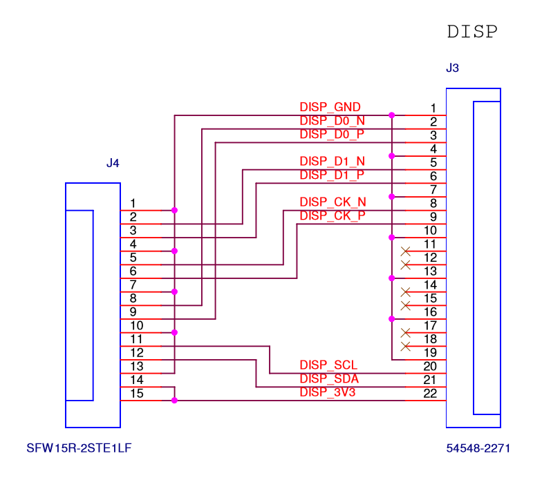
| Pin | Назначение |
|---|---|
| 1 | DISP_GND |
| 2 | DISP_D1_N |
| 3 | DISP_D1_P |
| 4 | DISP_GND |
| 5 | DISP_CK_N |
| 6 | DISP_CK_P |
| 7 | DISP_GND |
| 8 | DISP_D0_N |
| 9 | DISP_D0_P |
| 10 | DISP_GND |
| 11 | DISP_SCL |
| 12 | DISP_SDA |
| 13 | DISP_GND |
| 14 | DISP_3V3 |
| 15 | DISP_3V3 |
Custom blocks
Scratch 2.0 also allows the creation of custom blocks, allowing code to be encapsulated and used (possibly multiple times) in a project. The code below shows a simple custom block called ‘jump’, which is used to make a sprite jump whenever it is clicked.
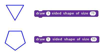
These custom blocks can also optionally include parameters, allowing further generalisation and reuse of code blocks. Here’s another example of a custom block that draws a shape. This time, however, the custom block includes parameters for specifying the number of sides of the shape, as well as the length of each side.
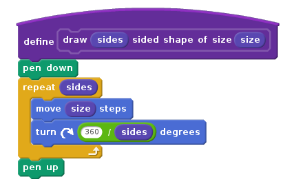
The custom block can now be used with different numbers provided, allowing lots of different shapes to be drawn.
Использование пинов и меры безопасности
Прежде чем что-то подключать к пинам интерфейса GPIO давайте разберемся какие напряжения/токи можно подключать к пинам в режиме входа и какие мы получим на выходе.
Пин GPIO в режиме входа:
- напряжение — 3.3В;
- уровень логической единицы (1) получаем начиная примерно с напряжения 1.8В;
- максимальный ток — 0.5мА!
Пин GPIO в режиме выхода:
- Напряжение — 0 и 3.3В (не 5В, как многие могут подумать);
- Ток — 2-16мА (по умолчанию 8мА);
- Максимальный суммарный ток нагрузки для всех задействованных пинов — 50мА!
Также важно помнить что:
- Внутренние буферы и ключи, которые подключены к пинам GPIO, НЕ защищены от перегрузки по напряжению и току;
- Пины питания с выходным напряжением 3.3В можно нагружать током не более 50мА;
- Пины с выходным напряжением 5В стараемся грузить не более чем на 500мА (для Model A) и не более чем на 300мА (для Model B) — почему так, расскажу ниже.
При проектировании устройств в которых используется большое количество пинов GPIO нужно обязательно делать развязку через дополнительные буферные схемы, преобразователи уровня напряжений, электронные ключи. Для чего это нужно? — чтобы обезопасить малинку от возможного повреждения (выгорания) электронных коммутаторов (ключей) и буферов внутри чипа.
А теперь давайте посмотрим что получится если мы подключим к трем портам GPIO и общему для них выводу 3.3В три светодиода, через каждый из которых будет протекать ток 20мА(сверхъяркие светодиоды): 20мА * 3 = 60мА — что является ПРЕВЫШЕНИЕМ максимально допустимого тока на пине 3.3В и небольшой перегрузкой для пинов GPIO (по 20мА на пин).
В данном случае для питания таких светодиодов нам нужно подключить к выводам GPIO дополнительные ключи на транзисторах или микросхемах, которые будут управлять светодиодами и не будут перегружать пины интерфейса.
Если на каждый из нескольких пинов GPIO мы повесим по светодиоду то можно их общую точку подключить к земле, в таком случае светодиод будет светиться если на пине будет присутствовать высокий (+3.3В) уровень, а для ограничения тока до 15мА последовательно светодиоду подключим токоограничительный резистор.
Пины с напряжением 5В подключены к основной шине питания 5В платы (после стабилизатора), большая нагрузка может повлиять на стабильность работы платформы в целом, а также вывести из строя внутренний стабилизатор напряжения +5В
Нужно с осторожностью отнестись к их использованию, допустимый ток не должен превышать 1А (без учета потребления самой платы): 1А — 700мА (ток потребляемый платой модели B) = 300мА
В действительности потребляемый малинкой ток во многом зависит от загруженности микропроцессора и видеопроцессора (графическая оболочка требует намного больше ресурсов чем консольный режим), а также от количества подключенных устройств к USB портам и их потребления. Значение общего потребляемого тока может варьироваться в пределах от 250мА до 1А.
Raspberry Pi, как и любая другая чувствительная электроника, может быть повреждена статическим электричеством. Перед работой желательно убрать накопившийся на теле статический заряд, снять с себя шерстяную одежду.
Перед пайкой модулей и плат желательно отключить их от разъема GPIO, будет неплохо если есть возможность выполнять монтаж паяльником на напряжение 36В (или ниже) с использованием понижающего трансформатора 220В — 36В и т.п.
Подведем небольшой итог по мерам безопасности:
- Перед работой снять с себя статический заряд;
- Желательно выполнять пайку электроники с отключенным разъемом GPIO;
- Не перегружать пины питания 3,3В (50мА) и не закорачивать их напрямую с другими пинами;
- Не перегружать пины питания 5В (300-500мА) и не закорачивать их напрямую с другими пинами;
- Исключить протекание тока величиной более 8-15мА через пины GPIO;
- Исключить попадание напряжения более 3.3В на пины GPIO;
- Подключать напрямую к Raspberry Pi не более 3х светодиодов (по 2-15мА каждый);
- Внимательно проверить правильность подключения перед подачей питания на схему и малинку.
Source/values properties
So how does the thing actually work?
Every GPIO Zero device has a property. For example, you can read a button’s state ( or ), and read or set an LED’s state (so is the same as ). Since LEDs and buttons operate with the same value set ( and ), you could say . However, this only sets the LED to match the button once. If you wanted it to always match the button’s state, you’d have to use a loop. To make things easier, we came up with a way of telling devices they’re connected: we added a property to all devices, and a to output devices. Now, a loop is no longer necessary, because this will do the job:
This is a simple approach to connecting devices using a declarative style of programming. In one single line, we declare that the LED should get its values from the button, i.e. when the button is pressed, the LED should be on. You can even mix the procedural with the declarative style: at one stage of the program, the LED could be set to match the button, while in the next stage it could just be blinking, and finally it might return back to its original state.
These additions are useful for connecting other devices as well. For example, a (LED with variable brightness) has a value between 0 and 1, and so does a potentiometer connected via an ADC (analogue-digital converter) such as the . The new GPIO Zero update allows you to say , and then twist the potentiometer to control the brightness of the LED.
But what if you want to do something more complex, like connect two devices with different value sets or combine multiple inputs?
We provide a set of device source tools, which allow you to process values as they flow from one device to another. They also let you send in artificial values such as random data, and you can even write your own functions to generate values to pass to a device’s source. For example, to control a motor’s speed with a potentiometer, you could use this code:
This works, but it will only drive the motor forwards. If you wanted the potentiometer to drive it forwards and backwards, you’d use the tool to scale its values to a range of -1 to 1:
And to separately control a robot’s left and right motor speeds with two potentiometers, you could do this:
UARTs and Device Tree
Various UART Device Tree overlay definitions can be found in the kernel GitHub tree. The two most useful overlays are and .
disables the Bluetooth device and makes the first PL011 (UART0) the primary UART. You must also disable the system service that initialises the modem, so it does not connect to the UART, using .
switches the Bluetooth function to use the mini UART, and makes the first PL011 (UART0) the primary UART. Note that this may reduce the maximum usable baud rate (see mini UART limitations below). You must also set the VPU core clock to a fixed frequency using either or .
The overlays , , , and are used to enable the four additional UARTs on the Pi 4. There are other UART-specific overlays in the folder. Refer to for details on Device Tree overlays, or run for descriptions and usage information.
For full instructions on how to use Device Tree overlays see this page. In brief, add a line to the file to apply a Device Tree overlay. Note that the part of the filename is removed. For example:
Controlling timings and resolutions
In firmware dated August 2018 or later, the config.txt entry that was previously used to set up the DPI timings has be superceded by a new parameter. If the parameter is not present, the system will fall back to using the parameter to ensure backwards compatibility. If neither are present and a custom mode is requested, then a default set of parameters for VGAp60 is used.
The and config.txt parameters are used to set either predetermined modes (DMT or CEA modes as used by HDMI) or a user can generate custom modes.
To generate a custom DPI mode, start here.
If you set up a custom DPI mode, then in config.txt use:
This will tell the driver to use the custom (older firmware uses ) timings for the DPI panel.
The parameters are specified as a space-delimited set of parameters:
Ground (gnd)
Ground is commonly referred to as GND, gnd or — but they all mean the same thing. GND is where all voltages can be measured from and it also completes an electrical circuit. It is our zero point and by connecting a component, such as an LED to a power source and ground the component becomes part of the circuit and current will flow through the LED and produce light.
When building circuits it is always wise to make your ground connections first before applying any power as it will prevent any issues with sensitive components. The Raspberry Pi has eight ground connections along the GPIO and each of these ground pins connects to one single ground connection. So the choice of which ground pin to use is determined by personal preference, or convenience when connecting components.
Распиновка CSI разъема камеры
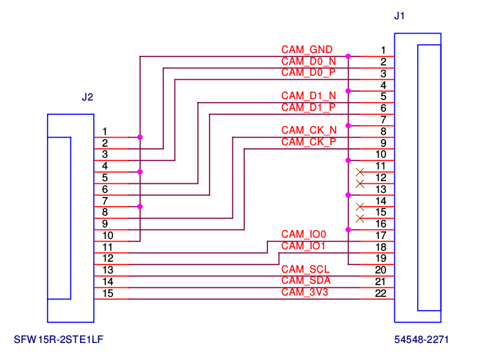
| Pin | Название | Описание |
| 1 | Ground | Ground |
| 2 | CAM1_DN0 | Data Lane 0 |
| 3 | CAM1_DP0 | |
| 4 | Ground | Ground |
| 5 | CAM1_DN1 | Data Lane 1 |
| 6 | CAM1_DP1 | |
| 7 | Ground | Ground |
| 8 | CAM1_CN | MIPI Clock |
| 9 | CAM1_CP | |
| 10 | Ground | Ground |
| 11 | CAM_GPIO | |
| 12 | CAM_CLK | |
| 13 | SCL0 | I²C Bus |
| 14 | SDA0 | |
| 15 | +3.3 V | Power Supply |
CAM1_CN и CAM1_CP
Эти контакты обеспечивают тактовый импульс для полос данных MIPI для первой камеры. Они подключаются к контактам MIPI Clock Positive (MCP) и MIPI Clock (MCN) ICC камеры. Эти тактовые сигналы обычно поступают от модуля камеры, генерируемого схемой MIPI.
SCL0 и SDA0
Меньшая последовательная шина, состоящая из контактов SCL и SDA, обеспечивает последовательную связь, которая позволяет пользователю управлять функциями камеры, такими как выбор разрешений. Эти контакты подключаются непосредственно к ведомому интерфейсу SCCB внутри IC камеры.
Вывод SCL обеспечивает стандартный входной тактовый сигнал последовательного интерфейса и стандартный последовательный интерфейс SDA для ввода/вывода данных.
Developing GPIO Zero
Nearly two years ago, I started the GPIO Zero project as a simple wrapper around the low-level RPi.GPIO library. I wanted to create a simpler way to control GPIO-connected devices in Python, based on three years’ experience of training teachers, running workshops, and building projects. The idea grew over time, and the more we built for our Python library, the more sophisticated and powerful it became.
One of the great things about Python is that it’s a multi-paradigm programming language. You can write code in a number of different styles, according to your needs. You don’t have to write classes, but you can if you need them. There are functional programming tools available, but beginners get by without them. Importantly, the more advanced features of the language are not a barrier to entry.
Заключение
Надеюсь было не скучно и информация, которую я представил в данной статье, будет полезна для ваших будущих проектов и экспериментов с платформой Raspberry Pi.
Что можно сделать после светодиода и кнопки? — можно подключить три светодиода и сделать небольшой бегущий огонь, также вместо светодиода можно подключить ключевой транзистор и малогабаритное электромагнитное реле для включения и выключения различных устройств с питанием от +12В или ~220В. Количество вариантов ограничивается только вашей фантазией и желанием.
- RPi Low-level peripherals (eLinux)
- RPi Tutorial EGHS:GPIO Protection Circuits
- Схемы, чертежи и документация на процессоры и периферию Raspberry Pi