Wemos d1 r2 обновление прошивки по wifi (ota)
Содержание:
Ответы на вопросы
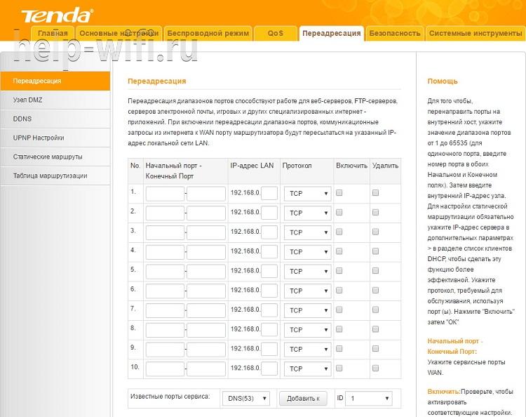
Не получается установка платы-при вводе URL адреса, кликаю и никакой реакции плата не установлена.
Чтобы «URL» появился в разделе плат, нужно предварительно прошить в модуль прошивку с OTA и не забыть в цикле крутить обработчик прошивки по воздуху. Разумеется, плата должна быть подключена к той же самой сети, что и компьютер. Т.е. сначала нужно установить библиотеки для ESP в систему, потом сконфигурировать и прописать скетч в саму плату, после этого она появляется как «порт» для прошивки.
После загрузки по воздуху в IDE выдаётся сообщение «: No Result!», но при этом скетч загружается нормально и работает. Почему так происходит?
Такое бывает. Можно попробовать обновить: IDE, утилиты для загрузки по воздуху, библиотеку Arduino для ESP. IDE не получает ответ от загрузчика о том, что загрузка произошла.
Зачем ставить Питон?
На питоне работает, как минимум компонент обновления и, скорее всего, компонент загрузки OTA.
Автор Владислав Кравченко
Шаг 4: Запускаем код
Теперь давайте рассмотрим пример для Wemos D1 Mini Pro
Обратите внимание, что есть три ключевых компонента, которые вам необходимо включить:
- char auth [] = «»; выбирается для вашего проекта (приложение Blynk).
- char ssid [] = «»; выбирается для сети к которой мы подключаемся (имя сети). Вы также можете раздавать со своего телефона.
- char pass [] = «»; выбирается для сети к которой мы подключаемся (пароль).
#define BLYNK_PRINT Serial

#include <ESP8266WiFi.h>

#include <BlynkSimpleEsp8266.h>

#include <DHT.h>

// You should get Auth Token in the Blynk App.
// Go to the Project Settings (nut icon).
char auth[] = "";

// Your WiFi credentials.
// Set password to "" for open networks.
char ssid[] = "";
char pass[] = "";

#define DHTPIN D4          // What digital pin we're connected to
#define DHTTYPE DHT11     // DHT 11<p>DHT dht(DHTPIN, DHTTYPE);
BlynkTimer timer;
float t;
float h;

void setup()
{
  // Debug console
  Serial.begin(9600);
  Blynk.begin(auth, ssid, pass);
  dht.begin();
  timer.setInterval(1000L, sendSensor);
}

void loop()
{
  Blynk.run();
  timer.run();
}


// This function sends Arduino's up time every second to Virtual Pin (5).
// In the app, Widget's reading frequency should be set to PUSH. This means
// that you define how often to send data to Blynk App.
void sendSensor()
{
  h = dht.readHumidity();
  t = dht.readTemperature(); // or dht.readTemperature(true) for Fahrenheit
//  l = analogRead(LDR);
  if (isnan(h) || isnan(t)) {
    Serial.println("Failed to read from DHT sensor!");
    return;
  }
  // You can send any value at any time.
  // Please don't send more that 10 values per second.
  Blynk.virtualWrite(V5, h);
  Blynk.virtualWrite(V6, t);
}
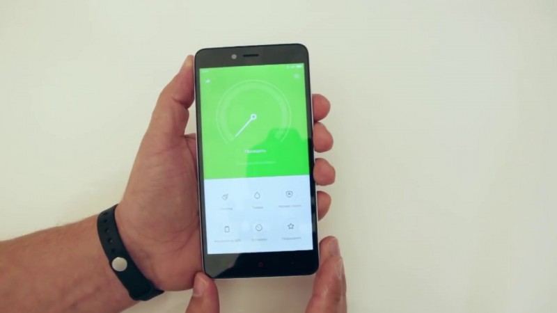
Шаг 2: Работа с приложением Blynk
Создание учетную запись Blynk
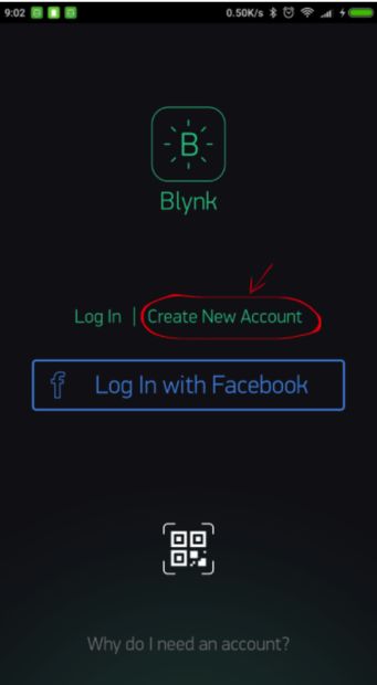
После загрузки приложения Blynk вам необходимо создать новую учетную запись. Эта учетная запись отделена от учетных записей, используемых для форумов Blynk, если у вас такой уже есть. Мы рекомендуем использовать реальный адрес электронной почты.
Зачем мне нужно создавать учетную запись?
Учетная запись необходима для сохранения ваших проектов и доступа к ним с нескольких устройств из любого места. Это также мера безопасности. Вы всегда сможете настроить свой собственный сервер Blynk.
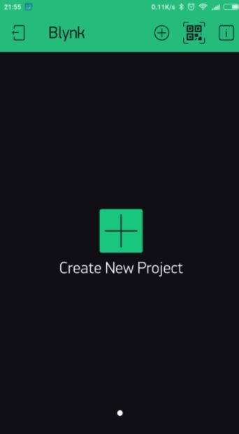
После того, как вы успешно вошли в свою учетную запись, начните с создания нового проекта.
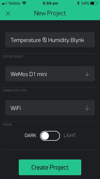
Дайте проекту имя и выберите подходящую плату (Wemos D1 Mini). Теперь нажмите «Создать».
Аутентификация
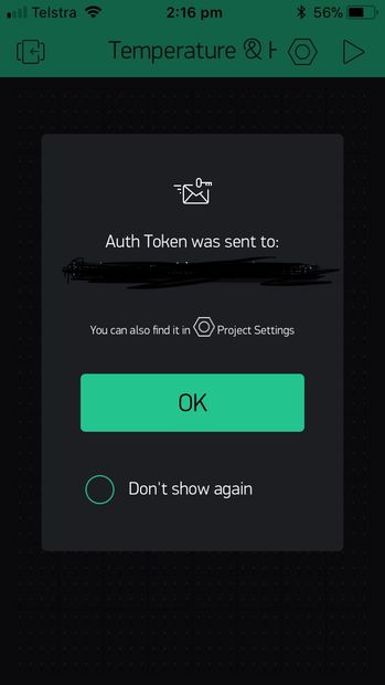
Ваш токен аутентификации будет отправлен вам по электронной почте, и вы также сможете получить к нему доступ в настройках вашего проекта. Новый номер будет создан для каждого создаваемого вами проекта.
Прошивки для esp8266 NodeMcu
В основу платформы загружена стандартная прошивка Node MCU, в которую встроен интерпретатор языка Lua. При помощи Lua-команд можно выполнять следующие действия:
- Подключение к Wi-Fi точке доступа;
- Работа в роли Wi-Fi точки доступа;
- Переход в режим глубокого сна для уменьшения потребления энергии;
- Включение или выключения светодиода на выходе GPIO16;
- Выполнение различные операции с файлами во флэш-памяти;
- Поиск открытой Wi-Fi сети, подключение к ней;
- Вывод MAC адреса;
- Управление пользовательскими таймерами.
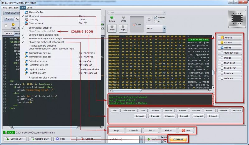
Для программирования NodeMCU можно использовать Arduino IDE или комплекс средств разработки SDK – ESPlorer. Этот комплекс обладает рядом отличий:
- Он может работать на множестве различных платформ;
- Обладает поддержкой нескольких открытых файлов;
- Позволяет подсвечивать код языка Lua;
- Возможность умной отправки файлов;
- Возможность поддержки нескольких видов прошивки одновременно.
Для обеспечения корректной и стабильной работы нужно обновить прошивку до последней версии. Существует несколько способов обновления – облачный сервис, Docker Image и компилирование в Linux. Каждый из этих способов обладает своими плюсами и минусами. Наиболее простым и понятным является первый способ.
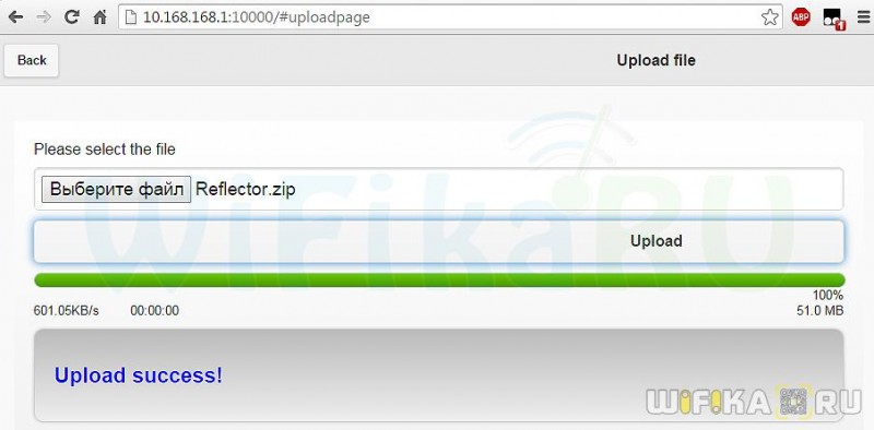
Сбор прошивки в облачном сервисе
После начала сборки придет письмо на почту, сигнализирующее о начале запуска процесса. Через некоторое время придет и второе письмо – будет предложено выбрать версию float (дробные числа) или integer (целые числа).
После перехода по полученной ссылке нужно будет скачать файл bin и поместить его в Resources – Binaries. Там будет расположен файл nodemcu_integer_0.9.5_20150318.bin, который нужно удалить. В итоге содержимое папки будет выглядеть следующим образом.
Обновление прошивки Node Mcu
Для правильной и стабильной работы платы требуется перезаписать esp_init_data_default.bin. Скачать его можно на официальном сайте. Нужный файл нужно поместить снова в систему для прошивки NodeMCU Flasher по пути Resources – Binaries, предварительно удалив из него старый файл.
Затем можно подключать NodeMCU и приступить к обновлению. Для начала нужно поменять настройки – в NodeMCU Flasher во вкладке Config нужно выбрать файл собранной прошивки вместо INTERNAL://NODEMCU.
Остальное оставить без изменений, перейти на Operations и нажать Flash. Как только окончится прошивка, нужно снова перейти на Config и в первой строке указать путь esp_init_data_default.bin. Также дополнительно указывается адрес, куда нужно переместить этот файл. Для модуля NodeMCU следует выбрать адрес 0x3FC000. После этого нужно снова вернуться на Operations и нажать Flash.
После этого нужно переформатировать всю файловую систему млаты. Для этого нужно запустить ESPlorer, обязательно поставить скорость обмена 115200 и перезагрузить NodeMCU. После всех вышеописанных действий будет новая версия прошивки. Отладочная плата полностью перепрошита и готова к работе.
Описание WeMos D1 R2
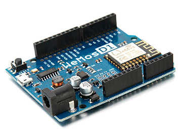 Плата WeMos D1, которая производится в Китае, выполнена на основе WiFi модуля ESP8266 ESP-12. На модуле имеется разъем под внешнюю WiFi антенну – благодаря этому можно расширить площадь покрытия сетью. Программирование платы осуществляется с помощью стандартной среды разработки Arduino IDE. Контроллер включает в себя процессор, периферию, оперативную память и устройства ввода/вывода. Наиболее часто микроконтроллеры применяются в компьютерной технике, бытовых приборах и других электронных устройствах. WeMos отличается дешевой стоимостью и простотой подключения и программирования.
Технические характеристики WeMos:
- Входное напряжение 3,3В;
- 11 цифровых выходов;
- Микро USB выход;
- 4 Мб флэш-памяти;
- Наличие WiFi модуля;
- Частота контроллера 80МГц/160МГц;
- Рабочие температуры от -40С до 125С.
Основными областями применения контроллеров WeMos являются температурные датчики, датчики давления и другие, зарядные устройства, пульты для управления различными бытовыми приборами, системы обработки данных, робототехника. К микроконтроллеру можно подключать дополнительные компоненты – индикаторы, сенсоры, светодиоды, которые позволяют реализовывать различные проекты и расширять их возможности.
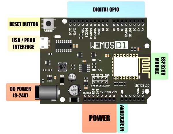
Распиновка модуля WeMos D1
- TX;
- RX;
- GND земля;
- 5В;
- 3v3;
- RST – reset, кнопка сброса;
- D0 – D8 –порты общего назначения GPIO. Все пины, кроме D0, поддерживают прерывание, ШИМ, I2C.
PlatformIO
Load the Sonoff-Tasmota base folder, including platformio.ini in PlatformIO.
Changes in the file platformio:ini
In platformio.ini we are going to add a new environment section and set the default environment to the newly created section.
First we create the new environment section.
- Copy the first environment section named «sonoff».
- Paste the section at the bottom of the file.
- Name the new section «wemos-d1-mini».
- Change the board type from esp01_1m to d1_mini.
The section should look like the following:
The next step is to set the default environment to our newly created environment. In the add the following line:
Your platformio.ini should look like this:
Change the user_config.h
Change the user_config.h to match your situation:
- Set the WiFi SSID and WiFi password
- Set the MQTT Username and MQTT password or disable MQTT
Краткое описание языка Lua
Язык Lua обладает простым синтаксисом и мощными конструкциями описания данных, которые основаны на массивах и расширяемой семантике. Этот мощный язык программирования используется для создания программного обеспечения, расширения различных игр. В отличие от остальных языков Lua обладает более гибкими и более мощными конструкциями.
Мигание светодиодами на Lua
Можно рассмотреть простейшую схему – мигание светодиодом. Этот пример поможет изучить работы с контактами GPIO. Светодиод нужно подключить как показано на схеме.
Затем нужно записать следующий скетч в левое окно ESPlorer:
pin_number = 1
gpio.mode (pin_number, gpio.OUTPUT) // установка рабочего режима на выход
gpio.write (pin_number, gpio.HIGH)// установка высокого уровня
gpio.write (pin_number, gpio.LOW)// установка низкого уровня
gpio.serout (1, gpio.HIGH, {+990000,990000}, 10, 1) // установка мигания светодиодом 10 раз
После нужно сохранить скрипт с названием init.lua. Сразу после этого начнется автоматическая загрузка написанного кода в отладочную плату и его выполнение. Если операция выполнена успешно, отладочная плата начнет мигать светодиодом.
Важно отметить, что плата самостоятельно выполняет скрипт, подключение к компьютеру нужно только для подачи питания
Choosing a Microcontroller with WiFi
First off, if you don’t need WiFi for your project, you do not need to use the Wemos or NodeMCU. A traditional Arduino Uno or Mega might be sufficient. So, for this article, I’m going to assume your project requires WiFi connectivity.
Related Article: WeMos WiFi Controlled Robot using L298N
Before we dive into the full review of what controller to use (Wemos D1 Mini or NodeMCU), I’m going to give a quick technical overview of each. If you already know about each controller, feel free to and skip down to the review portion.
Wemos D1 Mini Technical Overview
The Wemos D1 Mini is a small microcontroller made by the Chinese company, Wemos Electronics. The D1 Mini is only one of six families that the Wemos company makes. You can learn more about their other products, here. For this article, when I say Wemos, I’m referring to the D1 Mini controller. Feel free to let me know in the comments below if you’d like to see a full review of all of the Wemos Electronics products.
Now, let’s talk tech specs for the D1 Mini.
The D1 Mini is a 4MB flash controller based on the ESP8266 chip. It includes 11 digital input/output pins (I/O) each with an interrupt, PWM, I2C (except D0). There’s also 1 analog pin (A0). It’s compatible with Arduino, NodeMCU, and MicroPython. And, it also has a built-in Micro USB port, which you can use for power or download programs.
Related Article: How to use Dweet.io with Wemos D1 Mini (Arduino Tutorial)
The controller weighs only 3g and has a very small footprint at 34.2mm long by 25.6mm wide. There is also an assortment of “shields” compatible with the Wemos, which are neat if you’re looking to create a rapid prototype.
Lastly, the Wemos D1 Mini is very affordable ($5-$10 per controller). You can find them on Amazon, Aliexpress, or Banggood for exceptionally good prices. If you are based out of the US, I recommend getting your Wemos from Amazon, or you’ll be waiting anywhere from 20-50 days to save $5. Depending on your scenario, it may or may not be worth the wait from Aliexpress or Banggood.
Now that we’ve spoken a bit about the Wemos D1 Mini, let’s review the tech specs for the NodeMCU.
NodeMCU Technical Overview
The NodeMCU chip is marketed as an “open-source, interactive, programmable, low cost, WiFi-enabled” controller. You can access the API documentation here.
The controller has 10 GPIO pins that can be PWM, I2C, or 1-wire. There’s also a built-in ADC for your analog devices. The NodeMCU has a slightly longer footprint than the Wemos D1 Mini at 48.0mm long by 23.88mm wide. And, it weighs about 50g vs the 3g of the Wemos D1 mini.
Sale
Lastly, the NodeMCU is slightly more expensive than the Wemos D1 mini at about $8 per chip. But, like the Wemos, the NodeMCU can be bought at Amazon, Aliexpress, and Banggood.
Related Article: NodeMCU, dweet.io, & Freeboard.io Tutorial for IoT
Another thing to note about the NodeMCU is that the GPIO PINs are referenced differently than the I/O pins in software. Therefore, GPIO5 is not pin 5 in the code. It’s pin D1. (Refer to the pinout diagram above.)
Technology is forever changing
I was recently informed about the upgraded ESP32 chip on some NodeMCU’s. (Shoutout to Javier Corado for mentioning this on Facebook!) This chip provides a much better spec in comparison to the ESP8266 (and for about the same price).
If you plan on using the NodeMCU, I recommend checking out the version with an ESP32.
- Small Footprint
- Lower Cost ~ $5/ea
- 11X GPIO (multi-purpose)
- Programmable with Arduino, NodeMCU, and MicroPython
- Not programmable with Lua
- Pins aren’t aligned with breadboard
- Programmable with Arduino, MicroPython, and Lua
- LOTS of documentation + API
- ESP32 Version with enhanced specs
- Larger Footprint & Weight
- Affordable, A few dollars more ~$8/ea
- 10X GPIO (multi-purpose)
- Reference I/O in code not GPIO
Related Article: WeMos WiFi Controlled Robot using L298N
Configure the Tasmota software
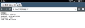
You can use a tool like fing or your wireless router to find the IP-address of your WeMos device.
The MAC-address starts with:
- 5C:CF:7F for the WeMos D1 mini and
- 60:01:94 for the WeMos D1 mini Pro
Open a browser and go to the IP-address of your WeMos device. You should be greeted with the familiar Tasmota configuration screen.
Set the device to «WeMos D1 mini» in the Configuration and save the configuration.
The device will reset, just wait for it to return.
WeMos pins vs ESP8266 pins
The WeMos boards have a different pin layout than the ESP8266 layout used in the Tasmota software. The table below shows the correlation:
| WeMos Pin | Function | ESP-8266 Pin |
|---|---|---|
| TX | TXD | TXD |
| RX | RXD | RXD |
| A0 | Analog input, max 3.3V input | A0 |
| D0 | IO | GPIO16 |
| D1 | IO, SCL | GPIO5 |
| D2 | IO, SDA | GPIO4 |
| D3 | IO, 10k Pull-up | GPIO0 |
| D4 | IO, 10k Pull-up, BUILTIN_LED | GPIO2 |
| D5 | IO, SCK | GPIO14 |
| D6 | IO, MISO | GPIO12 |
| D7 | IO, MOSI | GPIO13 |
| D8 | IO, 10k Pull-down, SS | GPIO15 |
| G | Ground | GND |
| 5V | 5V | — |
| 3V3 | 3.3V | 3.3V |
| RST | Reset | RST |
WeMos DHT11 Shield
To configure the DHT11 shield we return to the Configuration screen. The DHT11 uses D4 on the WeMos and therefore GPIO2 on the ESP8266.
Set GPIO2 to DHT11 like below:
After saving the configuration and the required reset we should see the following screen:
WeMos Relay and Button Shield
To configure the Relay and Button shield go to the Configuration screen. The Relay uses D1 on the WeMos and therefore GPIO5 on the ESP8266. The Button uses D3 on the WeMos, GPIO0 on the ESP8266.
Set GPIO5 to Relay and the GPIO0 to the Button:
Both the webinterface and the button can now be used to toggle the relais on and off.
Код программы
Для того чтобы настроить загрузку прошивок OTA, необходимо открыть скетч BasicOTA из примеров для Arduino от WeMos.
#include <ESP8266WiFi.h>
#include <ESP8266mDNS.h>
#include <WiFiUdp.h>
#include <ArduinoOTA.h>

const char* ssid = "..........";
const char* password = "..........";

void setup() {
  Serial.begin(115200);
  Serial.println("Booting");
  WiFi.mode(WIFI_STA);
  WiFi.begin(ssid, password);
  while (WiFi.waitForConnectResult() != WL_CONNECTED) {
    Serial.println("Connection Failed! Rebooting...");
    delay(5000);
    ESP.restart();
  }

  // Port defaults to 8266
  // ArduinoOTA.setPort(8266);

  // Hostname defaults to esp8266-
  // ArduinoOTA.setHostname("myesp8266");

  // No authentication by default
  // ArduinoOTA.setPassword("admin");

  // Password can be set with it's md5 value as well
  // MD5(admin) = 21232f297a57a5a743894a0e4a801fc3
  // ArduinoOTA.setPasswordHash("21232f297a57a5a743894a0e4a801fc3");

  ArduinoOTA.onStart([]() {
    String type;
    if (ArduinoOTA.getCommand() == U_FLASH)
      type = "sketch";
    else // U_SPIFFS
      type = "filesystem";

    // NOTE: if updating SPIFFS this would be the place to unmount SPIFFS using SPIFFS.end()
    Serial.println("Start updating " + type);
  });
  ArduinoOTA.onEnd([]() {
    Serial.println("\nEnd");
  });
  ArduinoOTA.onProgress([](unsigned int progress, unsigned int total) {
    Serial.printf("Progress: %u%%\r", (progress / (total / 100)));
  });
  ArduinoOTA.onError([](ota_error_t error) {
    Serial.printf("Error: ", error);
    if (error == OTA_AUTH_ERROR) Serial.println("Auth Failed");
    else if (error == OTA_BEGIN_ERROR) Serial.println("Begin Failed");
    else if (error == OTA_CONNECT_ERROR) Serial.println("Connect Failed");
    else if (error == OTA_RECEIVE_ERROR) Serial.println("Receive Failed");
    else if (error == OTA_END_ERROR) Serial.println("End Failed");
  });
  ArduinoOTA.begin();
  Serial.println("Ready");
  Serial.print("IP address: ");
  Serial.println(WiFi.localIP());
}

void loop() {
  ArduinoOTA.handle();
}
Затем настроить параметры для подключения к сети Wi-Fi, а именно имя сети и пароль доступа. Далее, загружаем скетч в устройство, отключаем его от компьютера и подключаем к внешнему источнику питания. После того как устройство с прошивкой загрузится и подключится к вашей Wi-Fi сети, то оно появится в виде сетевого устройства в меню выбора портов для взаимодействия с устройством. Дополнительно можно настроить такие параметры, как пароль доступа к устройству для обновления, номер порта и прочее.
Ну и собственно все. В дальнейшем можно встроить функциональность OTA в ваш код или же нарастить свой код используя BasicOTA как материнский контейнер. Обновление по воздуху будет работать в том случае, если будет вызываться соответствующий метод ArduinoOTA в цикле loop. Если ваша прошивка слишком сложная, содержит длительные циклы или занята какими-то сложными расчетами, то есть риск того, что обновление не будет подхватываться с первого раза. Поэтому стоит соблюдать баланс интересов в вашей прошивке.
Wemos D1 Release 1 (R1) and Release 2 (R2)~
Here you can find information for the big brother of the Wemos D1 mini which can be found here.
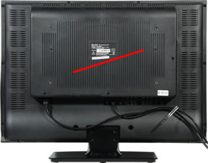
R1 vs. R2 — The Difference
When you take a look at the figure 1 you will see it with one blink of the eye thet the old Wemos is different against the new verion R2. The old version has an ESP8266 12B or 12E model. The new one has a ESP8266 12F model on the pcb board. You see this in the defference of the Wifi antenna. Here is a Wiki link to the different ESP8266 modules. The next part for R2 are the 2×4 solder pins for the serial and I2C interface which is not on the old model R1. The techncal data/specifiactions are the same. SO as you see they look like an Arduino UNO inculding the stacks to mount different shields. Later i will give more information over shields which i have tested and there are a lot of them.
Figure 1: WeMos D1 R1 vs. WeMos D1 R2
Settings in Arduino IDE (v1.8.7):
Both releases
First we will check that the right json index file is chosen. For that open File -> Preferences. Search for «Additional Boards Manager URLs:» (Figure 2). There you have an input filed. If that field is empty add this to it via copy&paste: http://arduino.esp8266.com/stable/package_esp8266com_index.json. Then close that window by hitting the OK button. If you have more then one link in that input field you have to use a comma after every link. So as done in Figure 2.
Figure 2: Additional Boards Manager URLs
Second we will look at the Boards Manager of Arduino IDE. As you can see in Figure 3 that the following things has to be installed. Possibile you have done this already together with the first installtion. Open Tools -> Board Selection -> Boards Manager, then search for esp8266 by ESP8266 Community. If you have fund it you will the same as in Figure 3. On the right side of that text you have searched for you can see the installed verion. Here in the sample it is 2.4.2. It is not installed you can make a choice under Select Version. If you start a new installation you can use the version 2.4.2. It works very well with both releases of Wemos D1.
Figure 3: Boards Manager
Settings to Flash a firmware on R1:
Open Tools -> Board and select the WeMos D1 R1 board. For the settings of release R1 see Figure 4. Don’t forget to select the right COM port so far your USB/Serial adapter is connected. Otherwise you can change this later after you have verified your code and you are ready to compile and flash. Then you have to connect your adapter and after the typical PING under Windows you can set your COM port.
Figure 4: Arduino Settings Wemos D1 R1
Settings to Flash a firmware on R2:
Open Tools -> Board and select the LOLIN(WEMOS) D1 R2 & mini board. And for the settings of release R2 see Figure 5, please. Don’t forget to set your COM port.
Figure 5:
As you can see the settings are the same only the name of the board is different. Internal there some different settings but we dont need to know that. Arduino IDE does the work for you.
Заключение
Платы на базе esp8266 – лучший способ организовать работу с сетью в ваших DIY проектах. Вы можете использовать большое количество разнообразных модулей и готовых плат, но WeMos – один из самых удобных способов. Плата похожа на Arduino Uno, достаточно легко подключается к датчикам и прошивается через Arduino IDE.
Уменьшенный аналог WeMos mini вообще можно назвать уникальным устройством, т.к. в очень компактном корпусе вы получаете не только почти все удобства и возможности Arduino, но и полноценный WiFi модуль. Можно даже обойтись без монтажа – просто вставляя различные модули расширения (шилды) WeMos как в матрешке, одну в другу. А недорогая цена делает эту плату абсолютным фаворитом для тех, кто делает умные устройства с возможностью выхода в интернет.