Terms of service
Содержание:
- Group/Ungroup Symbol
- Please note that the simulation tool in EasyEDA is primarily for analogue circuit simulation.
- Route Tracks
- The relationship between spice models and device datasheets
- Proteus Design Suite — программа схемотехнического моделирования, которая вам нужна, если вы студент инженерного факультета или специалист в этой области
- How to find simulatable parts in EasyEDA
- Via
- Pad attributes
- PCB
- Основные возможности EasyEDA
- Различные подходы в проектировании схем
- What if there is no model available for a device?
- Layer Manager
- Local Auto Router
- Заключение
Group/Ungroup Symbol
On the Wiring Tools palette there is the Group/Ungroup Symbol… button.
Just like the Symbol Wizard, this tool is also for you to quickly create schematic library symbols.
Here’s how.
-
Place Pins and other objects such as rectangle
-
Select them, and click the “Group/Ungroup Symbol” icon
-
Type the prefix and name, press OK, done. A part is created.
So what does Ungroup do? Try selecting a symbol and then click the Group/ungroup command to see what happens!
Note:
The symbol you created in the schematic will not be saved in the personal libraries, if you want to use it repeatly, please create a Symbol via: Top Menu — File — New — Symbol.
Please note that the simulation tool in EasyEDA is primarily for analogue circuit simulation.
Whilst there are models for a few small to medium scale integration logic devices available in the Spice Simulation library, it is generally not practical to model the following types of devices in EasyEDA:
-
Analogue to Digital Converters (ADC);
-
Digital to Analogue Converters (DAC);
-
Devices that use Serial Interfaces such as I2C or SPI for communications and configuration;
-
Microprocessors and microcontrollers including Arduino or similar types of modules;
-
FPGA;
-
State Machines;
-
Look Up Tables or ROM;
-
RAM;
-
Large and Very Large Scale Integrated devices and processing functions;
-
IBIS models (unless converted into Spice models by some 3rd party tool).
Route Tracks
In the schematic editor, we use Wire or the Hotkey to connect Pins, in a similar way in the PCB editor, we use Track to connect Pads. Track allows you to draw PCB tracks and can be found on the PCB Tools palette or using the Hotkey (not T).
Some Tips about Track
-
Single click to start drawing a track. Single click again to pin the track to the canvas and continue on from that point. Right click to end a track. Double right-click to exit track mode.
-
Drawing a track at the same time as using a hotkey(for example hotkey ) for changing the active layer will automatically insert a Via:
If you start drawing a track on the top layer, you will see it drawn in red, then press the B key to change to bottom layer and you will see EasyEDA insert a grey via and then the track will continue being drawn but now on the bottom layer in blue.
Pressing the + or — Hotkeys when drawing the track will change the width of the track on the fly. Use the hotkey TAB to change the track width.
Double clicking on a drawn section of the track will add a new vertex at that point. You can drag the vertex to form a new corner. And you can right-click the point and delete it.
Click to select the track and then Click and Drag on a segment of the track to adjust the segment between vertices.
-
When the track’s corner is a right Angle, drag the track next to the right Angle node to make a bevel. Instead of dragging a node directly, dragging a node directly will drag the entire track.
-
Selected a track, you can delete its node point.
Pressing the L Hotkey when drawing the track will change the track’s Route Angle on the fly. And you can change Route Angle on the Canvas Attributes of the right panel before the next drawing.
You can change inflection direction when routing, just press Space key.
If you want to route a track and use “L”, and the then press “+”, you will get two different size track segment. or press “SHIFT+W”.
If you want to create the solder mask aperture for the track, you can use “Expose Copper” when you select the track on the right-hand panel. The solder mask will bigger 4mil than the track.
And if you want to create the slot hole, you can route a track, and then right-click the “Convert to Board Cutout” menu.
You can make track routing width follow design rule, after enable the design rule option.
-
Right-click the track, you can select the track connection or a whole same net tracks.
-
If you want to the whole track, you can press and move it.
-
You can disable the DRC boundary at Desgin Rule. The size follow the rule.
-
If you want to continue routing for a net, you can disable the “Terminate Routing Automatically” option at “Setting — System Setting — PCB”.
-
Set up Remove Loop while routing, it only works on copper layer.
-
Using Routing Conflict as “RoundTrack” will help you finish routing quickly.
-
When edit the footprint document, you can set up the “Cut Silkscreen” to avoid the silkscreen track overlap the pad.
Track Length
-
When a track is selected, you can find its Length attribute in the right panel.
-
At left-hand Design Manager, click a net, will pop up a dialog to show you this net track length.
-
Click a track, press hotkey H will keep hightlight this track and net, and show this net’s length.
Delete a Segment from a Track
-
While routing, if you want to undo previous track path, you can press key “Delete” or “Backspace”.
-
Move your mouse to the segment which you want to delete, click it, then hold and double click it. the segment will be removed. Or right-click delete the node.
-
Right-click the track node to delete the track
-
Click the track, right-click delete it, or press “Delete” key directly.
DRC outline
When you routing a track on the signal layer, you will see an outline around the first track, it is the DRC outline, the clearance from outline to the track edge depends on your Design Rule(DRC) clearance setting.
The relationship between spice models and device datasheets
Although some of the device models in EasyEDA have been specially written so that the user can easily tailor them to simulate a range of devices by editing parameters that can be found directly in — or inferred from — device datasheets (see: About the relationship between spice models and real world behaviour below), most of them are off-the-shelf models from the device manufacturers.
It is important to understand that, for many of these off-the-shelf models, the underlying equations and therefore the .model parameters and .subckt definitions bear little relationship to the sort of information that is given in typical component datasheets. Therefore it is usually not possible to take a device datasheet and simply write down a device models from the information given in it.
Whilst it is possible to extract spice parameters for a variety of devices from device datasheets and from actual device measurements, it is beyond the scope of this document to describe how this can be done.
More information about what the model parameters mean in diodes, bipolar transistors and MOSFETs, is available from:
with individual slide sets:
For more detailed information about bjt’s in particular, this book:
is available from:
And:
Another excellent (and free) book about transistor modelling, is available by going to:
and registering to get a copy of:
More information about ngpsice is available from here:
More information about Larry Nagel and SPICE is available from here:
Larry’s PhD dissertation Dissertation:
Laurence W. Nagel., “SPICE2: A Computer Program to Simulate Semiconductor Circuits,”
Memorandum No. ERL-M520, University of California, Berkeley, May 1975.
is actually very readable and instructive.
For more information about electronic circuit simulation and spice in particular, see:
And:
Proteus Design Suite — программа схемотехнического моделирования, которая вам нужна, если вы студент инженерного факультета или специалист в этой области
Голосуйте
…10987654321
Средняя
8/10
(627 Всего голосов)
Скачать
Название Proteus не звучит многим людям. Если вы работаете в области медицины, вы, вероятно, слышали о нем, потому что это вид бактерий, который включает в себя различные виды, такие как mirabilis или vulgaris, которые проживают в нашем пищеварительном тракте. Но помимо микробиологии, в секторе программного обеспечения, это одна из самых известных программ схемотехнического моделирования, особенно знакома студентам-инженерам и специалистам в области электроники, способной предложить нам усовершенствованное моделирование электронных схем и микропроцессоров.
Это один из самых полных электронных наборов инструментов на рынке, так как в его версии 8.5 (самой новой) он позволяет нам создавать с нашего ПК все виды PCB или печатных плат, используя почти 800 различных микропроцессоров, и моделировать их реальное функционирование прямо из схематического представления схемы. И, как не могло быть иначе в современные времена, он интегрирует инструменты, с помощью которых мы можем проектировать и моделировать в среде Arduino, одной из самых популярных плат.
Основные компоненты Proteus Design Suite
Это программное обеспечение включает в себя два основных компонента, вокруг которых вращается вся работа программы:
- ISIS: аббревиатура от Intelligent Schematic Input System или Интеллектуальная Система Ввода Схем. Программа позволяет нам проектировать электрические схемы, включая всевозможные компоненты, такие как резисторы, катушки, конденсаторы, источники питания и даже микропроцессоры.
- ARES: сокращение от Advanced Routing and Editing Software или Расширенное Программное Обеспечение для Редактирования и Трассировки. Этот инструмент предназначен для проектирования печатных плат или PCB, с функциями трассировки, локализации и редактирования электронных компонентов.
Где я могу скачать ISIS и ARES? Вы не можете использовать их в качестве автономных приложений, поэтому для максимально эффективного использования всех функций, вам придется воспользоваться полной версией Proteus, которая, несмотря на то, что является платной, имеет пробную версию, доступную на официальном веб-сайте Labcenter Electronics, чтобы вы могли опробовать все его функции, прежде чем принять решение, покупать его или нет.
Помимо этих двух программ, это программное обеспечение поставляется вместе с различными модулями, такими как VSM, которые, интегрированные в ISIS, позволяют нам моделировать различные функции интегральных схем в реальнои времени, или Electra, модуль автотрассировки, автоматической расстановкой компонентов на печатной плате, в поисках оптимального пути для улучшения скорости схем.
Какой из них лучше? Proteus или Multisim?
Это вечное сомнение студентов и специалистов в области электроники, когда речь заходит о выборе программы для моделирования электронных схем, и, как всегда, универсального ответа, который бы удовлетворял их всех, не существует, поскольку он в основном зависит от использования, данного приложению.
Например, если вы ищете программу для аналогового и цифрового моделирования цепей, продукт, разработанный National Instruments Corporation, может удовлетворить ваши потребности, так как это лучшее программное обеспечение в этой категории. Однако если вы больше увлекаетесь моделированием микропроцессоров, Multisim, вероятно, не будет покрывать ваши нужды, и именно здесь нужно использовать Proteus, поскольку он включает в себя много библиотек, которые позволяют вам моделировать различные модели. Так что каждый хорошо разбирается в разных вещах, и выбор за вами.
Что нового в последней версии
- Добавлен веб-поиск в библиотеку и путь автозаполнения.
- Улучшена структура панели.
Требования и дополнительная информация:
Antony Peel
9/10
Мария Жушков
Языки ПО
Автор
Labcenter Electronics
Обновление
3 месяца назад
Последний пересмотр
07/22/20
Размер
25.8 MB
How to find simulatable parts in EasyEDA
How to find spice symbols (which have models already associated with them)
From V4.1.3. — except for the simple passive R, L, C and the voltage and current source devices — most of the schematic symbols for the active devices shown in the left hand panel under the button no longer have spice models associated with them.
Schematic symbols with spice simulation models attached to them can now be found using the:
Libraries button in the left-hand panel
or;
SHIFT+F in any editor window.
then click on , hover the mouse over the class then slide down and click on any of the grey buttons under the Spice Simulation heading:
You will find a list of all the spice models (.model) and spice subcircuits (.subckt) currently available for EasyEDA here:
Some of the models in this list are already used by the Spice Simulation symbols referred to above. Some of these models have no dedicated symbols but they can be associated with existing symbols just by editing the symbol names.
Alternate models can be assigned to the Spice Simulation symbols by changing the names of the symbols to that of the new model and also — depending on whether the new model is a .model or a .subckt defined model — by pressing the key and changing the spice prefix.
You can enter these model names into any approriate Spice Simulation symbol and then set the spice prefix to the prefix approriate for the model (See: Ngspice model types in: )
The steps to do this are described in:
but see also:
It is also possible to import spice models from 3rd party sources to use with the Spice Simulation symbols from these list.
The steps to do this are described in:
but see also:
In the case of there being a 3rd party model available but for which there is no suitable symbol in EasyEDA then it is quite straightforward to create a spice symbol for it within EasyEDA either by editing an existing symbol or by creating a new one from scratch.
The steps to do this are described in:
but see also:
Note that not all 3rd party models are compatible with ngspice syntax. versions of models should run out of the box. models may require modifications to make them work in EasyEDA.
Please post to:
in the forums for help on this.
However, we have created models — unique to EasyEDA — for a number of parts, such as the , , and . So, although it is not always possible or practical to build a model, if there is a part for which you particularly need one then please contact Support to discuss your requirements.
Via
When you want to lay a multilayer PCB, you need to add Vias for nets getting through layer and layer.
Place a Via on a Track
When placing a on a track, the track will be cut to two segments, and the via net will follow track’s net. Placing two vias on a tracks, you will get three segments, then you can change one segment to other layer id, or remove one of them.
Place Multiple Vias
Click the copper area outline, click the “Add/Remove Vias” button. this feature needs the same net copper areas on two and more layers in the same time, the cross area will add the vias.
Notice:
EasyEDA only support the through via for all layers, doesn’t support the Buried Blind/via.
Pad attributes
You can add pads using the Pads button from the Footprint Tools palette or using the hotkey.
After selecting one of the pads, you can view and adjust its attributes in the right hand Properties panel.
Number: Remembering the pin numbers you set in the schematic symbol in your Schematic symbol: to connect those schematic symbol pins to the pads in your PCB footprint, the pad numbers you set here in the Footprint footprint must be the same.
Shape: Round , Rectangular , Oval and Polygon.
EasyEDA supports four shapes: , , and .
- PAD will give your more space.
- PAD will let you to create some strange pad.
Like in the image below, you can edit the PADs points when you select a PAD
Layer: If the pads are part of a SMD footprint, you can set it to Top layer or Bottom layer. For through hole components you should set it to Multi-Layer.
Net: You don’t need to enter anything here because at present this footprint is not connected to anything in a circuit.
Width and Height: When the shape is set to Round, Width will equal Height.
Rotation: Here you can set the Pad’s rotation as you want.
Hole(D): This is the drill hole diameter for a through hole pad. For a SMD Pad, set this to zero.
Center-X and Center-Y: using these two attributes, you can set the pad’s position with more precision, compared to using the mouse.
Plated: Yes or No. when the pad is multi-layer pad, if it set the plated as no, this pad top side and bottom side will not be connected together.
PCB
| DocType | Shortcut | Function |
|---|---|---|
| PCB | W | Draw Track |
| PCB | U | Draw Arc |
| PCB | C | Draw Circle |
| PCB | N | Draw Dimension |
| PCB | S | Draw Text |
| PCB | O | Draw Connect |
| PCB | E | Draw copperArea |
| PCB | T | Change To TopLayer; Change selected part to toplayer |
| PCB | B | Change To BottomLayer; Change selected part to bottomlayer |
| PCB | 1 | Change To Inner1 |
| PCB | 2 | Change To Inner2 |
| PCB | 3 | Change To Inner3 |
| PCB | 4 | Change To Inner4 |
| PCB | P | Place Pad |
| PCB | Q | Change canvas unit |
| PCB | V | Place Via |
| PCB | M | Measure |
| PCB | H | Highlight Net all the time, press it again cancel highlight |
| PCB | L | Change Route Angle |
| PCB | — | Decrease Routing Width; Switch to the forward signal layer |
| PCB | + | Increase Routing Width; Switch to the next signal layer |
| PCB | * | Cycle switch to the next signal layer |
| PCB | Delete | Delete selected object; Undo the track when routing |
| PCB | ALT– | Decrease Snap Size |
| PCB | ALT++ | Increase Snap Size |
| PCB | CTRL+R | Depend on reference point for copy object repeatly |
| PCB | CTRL+L | Open layer manager |
| PCB | CTRL+Q | Hide/show network text |
| PCB | SHIFT+M | Remove All Copper Area fill data |
| PCB | SHIFT+B | Rebuild All Copper Area |
| PCB | SHIFT+D | Move Object(s) by reference point |
| PCB | SHIFT+G | Display track length while routing |
| PCB | SHIFT+W | Show favorite track width while routing |
| PCB | SHIFT+R | Change routing conflict |
| PCB | SHIFT+S | Toggle layers which is not active |
| PCB | SHIFT+Double Click | Delete selected track segment |
| PCB | CTRL+SHIFT+V | Paste object(s) and keep the prefix, and hide the ratline layer |
| PCB | CTRL+SHIFT+SPACE | Change routing angle, same as hotkey L |
Основные возможности EasyEDA
Далее будет подробное описание возможностей программы с примерами.
Фильтр
Перед использованием фильтра вам нужно выбрать нужный модуль на левой навигационной панели, а затем вы можете быстро и легко найти проекты, файлы, детали и посадочные места, просто набрав несколько букв заголовка. Например, если вы хотите найти все файлы, содержащие «NE555» в заголовке, просто введите «555», без учета регистра.
Фильтр ищет только заголовки и названия проектов, файлов и деталей. Он не выполняет поиск в полях Описание и Содержание.
Нажмите X, чтобы очистить фильтр.
Панель навигации
Панель навигации очень важна для EasyEDA, именно здесь вы можете найти все свои проекты, файлы, детали и элементы footprint.
Проектздесь, вы можете найти все свои проекты, которые являются частными или общедоступными, или разрабатываются чужими.
За исключением System IC, эти параметры имеют меню содержимого. Например, если вы перейдете в «Мои проекты» и щелкните правой кнопкой мыши на элементе, вы получите древовидное меню, например:
EELib
EElib означает «Библиотеки EasyEDA». Он содержит множество компонентов с имитационными моделями, многие из которых были разработаны для EasyEDA, чтобы упростить процесс моделирования.
- Design Manager
Менеджер дизайна, вы можете легко проверить каждый компонент и сеть, и он обеспечит проверку правил проектирования, чтобы помочь вашему дизайну.
Libraries (Библиотеки)
Содержит условные обозначения и контуры печатной платы для многих легкодоступных компонентов и проектов. Ваши собственные библиотеки и модули появятся здесь.
LCSC (Love Components Save Cost)
Если вы хотите купить дополнительные компоненты и закончить свою печатную плату, компания EasyEda предлагает приобрести модуль LCSC. LCSC.com и EasyEDA один и та же компания.
JLCPCB
Компания по производству печатных плат, специализируется на быстром прототипе печатной платы и мелкосерийном производстве. Доступные, качественные платы серийного производства, полностью изготовленные в Китае. JLCPCB.com, LCSC.com и EasyEDA — это одна и та же группа компаний.
Атрибуты холста
На правой части рабочей панели представлено меню «Атрибуты холста». Можно настроить цвет фона и сетки, а также стиль, размер, видимость и атрибуты сетки. Область холста может быть установлена непосредственно шириной и высотой или из доступных предустановленных размеров.
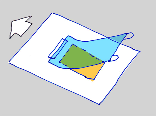
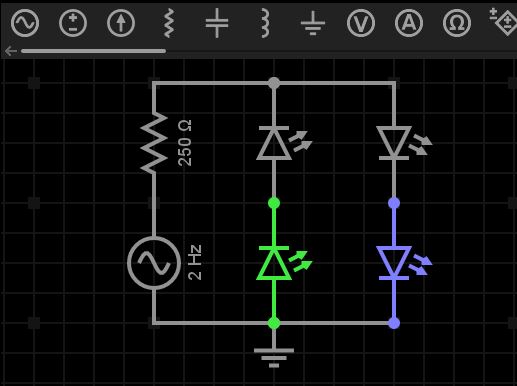
Различные подходы в проектировании схем
Сейчас мы должны подключить все это к одному из GPIO нашего модуля ESP8266 и тут можно пойти разными путями. Можно сделать по-старинке и соединить на схеме наши светодиод и резистор с выходом GPIO модуля на левой части схемы — именно так раньше и делали (многие продолжают делать так и сейчас, и не только в России). Получаются вот такие схемы:
Схема радиоприемника Спидола-230
Но из зарубежья к нам пришло новое веянье — схемы, оформленные по-другому:
Схема Wemos D1 mini PRO 128Mbit (16 Мегабайт)
Такие схемы оформлены более модульно, не загромождены множеством соединительных линий от края до края. Соединение модулей производится через именованные электрические связи (проводники) с соответствующей маркировкой. Такие схемы менее привычны и некоторые радиолюбители считают, что они не позволяют увидеть сразу все детали. Попробуйте ответить на вопрос: какие элементы подключены к VCC на этой схеме? Можно легко упустить из виду какой-то модуль. Однако, если вы планируете выходить на международный рынок — не обязательно продавать что-либо, даже если вы просто размещаете свой проект в публичный доступ, то имеет смысл задуматься над выбором, и, возможно, сделать схему в современном виде, общепринятом в международном сообществе. Однако, это остается, безусловно, на ваше усмотрение.
What if there is no model available for a device?
Not all devices have spice models that can be run in ngspice. There are a number of possible reasons for this.
1) Some models are encrypted and can only be run in certain proprietary simulation tools;
2) Some proprietary simulators support models that are not available in ngspice;
3) Some devices have models that only run in specific non-spice based simulation tools and which, for whatever reason, cannot be translated into spice models;
4) Some devices do not have publically available models;
5) Many devices predating the creation of the original spice program do not have models;
6) Models for some devices simply do not exist because the manufacturers have never created them;
7) Some models may be unavailable in EasyEDA because they are restricted by copyright or end user licenses so they can only be run in certain proprietary simulation tools or cannot be shared publicly.
In cases (1) to (3), there is no way they can be run in ngspice. They must be run in the simulation tools for which they were written.
In cases (4) to (7), it is sometimes possible to find an equivalent, alternative or similar device for which a spice model is available. The user must exercise caution and use their judgement in deciding if such an approach offers satisfactory simulation results.
It must be noted that spice was not originally written with support for thermionic devices (valves or tubes) so models for such devices exist only in .subckt form. They are usually created by enthusiasts rather than manufacturers and so they (a) can be hard to find and (b) should be used with caution. EasyEDA does have a library of valve models gathered from sources that we believe have written reasonably accurate models.
Note that models obtained from manufacturers are often subject to copyright restrictions. Please respect any copyright notices contained either in end user license agreements that may have to be accepted prior to the granting of access to a downloadable copy of a model or in the models themselves.
Similarly, models contained in the libraries of commercial simulation tools are subject to copyright restrictions.
It is often possible to find device models offered in forums, discussion groups and various online collections of models. Again, the user must exercise caution and use their judgement in deciding if such models really are suitable. Often it is not possible to establish where they originate from so their validity is very hard to verify. It is also possible that such models have been copied in breach of the originators’ copyright.
Where possible, models should be obtained from the device manufacturer but please read their End User License Agreements carefully to avoid falling foul of their copyright restrictions.
Finally, note that not all 3rd party models are compatible with ngspice syntax. Spice3 (.sp3) versions of models should run out of the box. Pspice models may require modifications to make them work in EasyEDA. TINA TI models generally take a lot of work to translate them into ngspice compatible models.
Layer Manager
You can set the PCB layer’s parameters at the Layer Manager.
Via Top Menu> Tools > Layer Manager…, Or Click Layers Tool gear icon. Or right-click the canvas — Layer Manager menu.
The Layer Manager dialog:
The Layer Manager setting only works for the current editing PCB.
Copper Layer: The copper layer of your PCB. EasyEDA support 34 copper layers. The more copper layers the PCB will be more expensive. The TopLayer and BottomLayer is default layer, can not be disable. If you want change the copper layers from 4 to 2, you must delete the inner layers objects first.
Display: If you don’t want a layer dosen’t display at “Layers Tool”, you can disable the checkbox. Notice: This option only hide the layer name on the “Layers Tool”, the objects of the hidden layer still exist, when you generating the Gerber, they will appear.
Name: Layers name. For the inner layer, you can define the name.
Type:
- Signal: Which is working for the signal. Such as Top and bottom layer.
- Plane: When the inner layer type is “Plane”, this layer will be copper pourred, if you want to separate the copper area you can draw the Track or Arc. You can treat this layer is a only has the copper area, but its easy than draw the copper area. The track you routed will generate the clearance when generating the Gerber. The “Plane” usually is using for the Power or Ground copper pour on the inner layer. You can set the net for the plane zone.Notice:When draw the track to separate the plane zone, the track start ponit and end point must over the middle line of the board oultine track. Otherwise, the plane zone will not be separated; When using the plane layer, the PCB can not exist two closed borad outline, only one closed board outline will generate the plane zone.
- Non-Signal:Such as silk screen, mechanical layer, document layer etc.
Color: You can define the color for each layer.
Transparency: You can change the layer transparency.
Layer Definination:
- TopLayer/BottomLayer: The top side and bottom side of the PCB board, copper layer.
- InnerLayer: Copper layer, routing track and copper pour.
- TopSilkLayer/BottomSilkLayer: Board silkscreen.
- TopPasteMaskLayer/BottomPasteMaskLayer: This layer is the layer used to make the stencil for the SMT pads, helping to solder. This layer has no effect on production if the board is not required to make the stencil.
- TopSolderMaskLayer/BottomSolderMaskLayer: The top and bottom cover layers of the board are typically green oil, which acts to prevent unwanted welding. This layer belongs to the negative film drawing mode. When you have wires or areas that do not need to cover green oil, draw them at the corresponding positions. After the PCB is generated, these areas will not be covered with green oil, which is convenient for operations such as tinning.
- BoardOutline: The board shape definition layer. To define the actual size of the board, the board factory will produce the board according to this shape.
- TopAssemblyLayer/BottomAssemblyLayer: Simplified outline of components for product assembly and repair. Used to export document printing, without affecting PCB production.
- MechanicalLayer: Record the information on the mechanical layer in the PCB design, and only use it for information recording. By default, the shape of the layer is not manufactured at the time of production. Some board manufacturers use the mechanical layer to make the frame when using Altium file to production. When using Gerber file, it is only used for text identification in JLCPCB. For example: process parameters; V cut path etc. In EasyEDA, this layer does not affect the shape of the border of the board.
- DocumentLayer: Similar to the mechanical layer. But this layer is only visible in the editor and will not be generated in the Gerber file.
- RatlineLayer: PCB network ratline display, this layer is not in the physical sense, in order to facilitate the use and set color, it is placed in the layer manager for configuration.
- HoleLayer: Similar to the RatlineLayer. For Hole(Non-Plated Hole) display.
- Multi-Layer: Similar to the RatlineLayer. For multi-layer hole(Plated hole) display. If the PAD setting layer property as mult-layer, it will connect with all copper layers.
- DRCErrorLayer Similar to the RatlineLayer. For DRC(Design Rule Error) marking dispaly.
Local Auto Router
EasyEDA suggest that using local auto router rather than using the cloud server, because when many users using cloud server, the cloud auto router will fail. Only support 64bit system.
For the local auto router, please follow the steps as below:
-
1.Download the local auto router server.EasyEDA:EasyEDA Router.zip(134MB)Supported OS:
- Windows7(x64) or later 64bit Windows
- Ubuntu17.04(x64) or other 64bit Linux, Linux recommend Deepin
- macOS(x64)
-
2.Unzip it to the User folder, such as driver D.
-
3.Configure the browser.Notice: Please use the latest Chrome or Firefox !!!
- 1)ChromeThe Chrome Browser don’t need to be configure, If the local auto router is unavailable, you have to upgrade Chrome to version 60.0.3112.78 or later.
-
2)Firefox
- 1.Type “about:config” into the address bar then press enter.
- 2.Search and double click the options as below (change the values to “true”):
-
4.Open the decompress folder, Start local Auto Router(don’t need to install, just run it and keep the command window open):
- Double click in Windows.
- Run on command terminal in Linux. Open the terminal, use the command to change the directory to the location, and type , then enter.
- Run on command prompt in MacOS. Open the terminal, use the command to change the directory to the location, and type , then enter.
-
5.Open the editor, open the PCB, Click the Auto Router icon at editor to start auto-router.If the local router server is available, the dialog will tell you. Click the Run button, the dialog will show the process.
Tips
Sometimes, if you can’t get it done, try the tips below.
- Make sure the net of PCB doesn’t contain the special charaters, such as ; ~ \ / = etc. the chrarter — and _ are supported.
- Make sure the board oultine is closed, doesn’t has board oultine overlap situation.
- Make sure there are no DRC cleance errors (short circuit issue), such as two different network pads overlapping, or different net pads in the same location within the footprint.
- Make sure no footprint outside the board outline.
- Make sure PCB rule doesn’t have 3 decimal places, EasyEDA auto router only support 2 decimal places.
- Skip the GND nets, add copper area to GND net.
- Use small tracks and small clearance, but make sure the value is more than 6mil.
- Route some key tracks manually before auto routing and ignore them when auto routing.
- Add more layers, 4 layers or 6 layers, but that will make the PCB more expensive.
- Change the components layout, make them have more space between each other.
- Don’t make any via/pad/solid region overlap the different net objects.
- Use local auto router rather than cloud server.
- Tell the error detail to us and download and send your PCB file as EasyEDA Source json file:https://docs.easyeda.com/en/Export/Export-EasyEDA-Source-File/index.htmlvia email.
Some professional people don’t like the auto router, because they think auto router is not professional, but you can use the auto router to check your placement to check the density of your PCB.
At present, the auto router is not good enough, suggest routing manually, we will improve it in the future.
Заключение
Эта статья получилась слишком большой и я искренне благодарен тем, кто смог дочитать ее до конца. Даже в этом объеме мне не удалось рассказать о многих интересных возможностях EasyEDA. Возможно, это получится в следующих материалах.
В целом, впечатление от EasyEDA у меня сложилось очень положительное, несмотря на некоторые недостатки, которые меня огорчили. Я вспоминаю те времена, когда я начал осваивать DeepTrace, и потратил намного больше времени на свою первую схему. Здесь же все оказалось много проще, при достаточно широких возможностях. Так что я плюсую EasyEDA.
Мне импонирует дух open source, которым пропитан сервис EasyEDA — это и публичные проекты и легкость их использования и открытый формат файлов выгрузки проектов, о котором мне не удалось рассказать в этой статье. Этакий гитхаб, только не для программ, а для плат. Кстати, поддержка контроля версий плат была бы очень кстати 🙂