J-link commander
Содержание:
- Windows
- Testing VCOM functionality and speed
- macOS
- Command line options
- Using J-Link Command Files
- ТЕХНИЧЕСКИЕ ХАРАКТЕРИСТИКИ J-LINK V9
- Limitations under Mac OS X
- Программатор J-Link v9 (JTAG/SWD)
- Setup External CFI NOR Flash
- Enumeration under Ubuntu running in VirtualBox fails
- Knowledge Base
- ModemManager
- Why J-Link?
- Embedded Software
- Batch processing
- Testing
Windows
The Windows file is a ZIP archive, named like . After unpacking it, a Windows executable file is obtained, named like .
- double click it to start the installation process
- enter the administrative password
- accept the license
- accept the destination folder ()
- accept the default USB driver
The result of the install is a folder (a new folder for each new version installed), and a set of driver files installed in the system folders, overwritten with each new install.
Please note that on Windows, SEGGER provides both graphical interface and command line versions (having the names suffixed with ) for most of their tools. For the J-Link plug-in it is recommended to use only the command line version of the J-Link GDB server ().
Testing VCOM functionality and speed
The VCOM functionality can be tested for by simply connecting the Tx pin with the Rx pin — creating a loopback that way — and starting a terminal application.
This leads to the Rx pin receiving the sent data meaning that VCOM is active and working.
- Create a loopback by connecting the Tx pin with the Rx pin.
- Make sure pins VTref and GND are connected to J-Link. For testing we recommend VTref = 3.3 V.
- Start a terminal application (e.g. HTerm) and establish a connection to the COM port.
- Use an oscilloscope to visualize the signals sent via the Tx pin and the Rx pin.
- Send data via VCOM using the given terminal application. Use the letter «U» (01010101 in binary) to create a regular square-wave signal.
The oscilloscope will show the same signal sequence for both, the Rx and the Tx pin, confirming the VCOM functionality.
The speed VCOM is operating at can also be determined with an oscilloscope, e.g. by measuring the duration of a single high state.
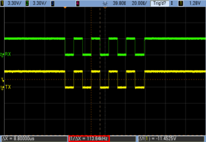
VCOM char ‘U’
macOS
The macOS download is an macOS package installer, like .
- double click it to start the installation process
- accept the license
- enter the administrative password, required to write in the global folder
The result of the install is a folder like (a different folder for each version) where all executables and libraries are stored; please note that, as for many macOS applications, no other driver files are installed in the system folders, but some symbolic links are created in the folder.
Be sure to update the path in Eclipse preferences page to point to the latest SEGGER J-Link software.

USB
On macOS, the USB subsystem automatically identifies and allows access to USB devices, without the need to maintain a manual list similar to the one used by UDEV in GNU/Linux. No other drivers or system configurations are required.
Command line options
J-Link Commander can be started with different command line options for test and automation purposes.
In the following, the command line options which are available for J-Link Commander are explained.
All command line options are case insensitive.
| Command | Explanation |
|---|---|
| Automatically start the target connect sequence. | |
| Passes a CommandFile to J-Link | |
| Passes a CommandFile to J-Link | |
| Pre-selects the device J-Link Commander shall connect to | |
| Commander exits after error | |
| Pre-selects the target interface | |
| Selects IP as host interface | |
| Passes a JLinkScriptFile to J-Link | |
| Sets IRPre and DRPre | |
| Sets logfile path | |
| Starts J-Link Commander in no GUI mode | |
| Sets the RTT Telnetport | |
| Connects to a J-Link with a specific S/N over USB. | |
| Passes a SettingsFile to J-Link | |
| Starts J-Link Commander with a given initial speed |
-AutoConnect
This command can be used to let J-Link Commander automatically start the connect sequence for connecting to the target when entering interactive mode.
Syntax
-autoconnect <1|0>
Example
JLink.exe -autoconnect 1
-CommandFile
Selects a command file and starts J-Link Commander in batch mode. The batch mode of J-Link Commander is similar to the execution of a batch file.
The command file is parsed line by line and one command is executed at a time.
Syntax
-CommandFile <CommandFilePath>
Example
See .
-Device
Pre-selects the device J-Link Commander shall connect to.
For some devices, J-Link already needs to know the device at the time of connecting, since special handling is required for some of them.
For a list of all supported device names, please refer to .
Syntax
-Device <DeviceName>
Example
JLink.exe -Device STM32F103ZE
Additional information
Selecting «default» as <DeviceName> will select the last known connected device.
-If
Selects the target interface J-Link shall use to connect to the target.
By default, J-Link Commander first tries to connect to the target using the target interface which is currently selected in the J-Link firmware.
If connecting fails, J-Link Commander goes through all target interfaces supported by the connected J-Link and tries to connect to the device.
Syntax
-If <TargetInterface>
Example
JLink.exe -If SWD
-IP
Selects IP as host interface to connect to J-Link. Default host interface is USB.
Syntax
-IP <IPAddr>
Example
JLink.exe -IP 192.168.1.17
Additional information
To select from a list of all available emulators on Ethernet, please use * as <IPAddr>.
-JLinkScriptFile
Passes the path of a J-Link script file to the J-Link Commander.
J-Link scriptfiles are mainly used to connect to targets which need a special connection sequence before communication with the core is possible.
For more information about J-Link script files, please refer to J-Link Script Files.
Syntax
JLink.exe -JLinkScriptFile <File>
Example
JLink.exe -JLinkScriptFile “C:\My Projects\Default.JLinkScript”
-JTAGConf
Passes IRPre and DRPre in order to select a specific device in a JTAG-chain. “-1,-1” can be used to let J-Link select a device automatically.
Syntax
-JTAGConf <IRPre>,<DRPre>
Example
JLink.exe -JTAGConf 4,1
JLink.exe -JTAGConf -1,-1
-Log
Set path to LogFilePath allowing the DLL to output logging information.
If the logfile already exists, the contents of the current logfile will be overwritten.
Syntax
-Log <LogFilePath>
Example
JLink.exe -Log C:\Work\log.txt
-NoGui
Starts the J-Link Commander in «no GUI»-mode.
Please note that license dialogs are not suppressed in this mode.
Syntax
-NoGui 1
Example
JLink.exe -NoGui 1
NOTE:
This command is not yet available. It will be available for Version 6.71d (beta) and V6.74 (release) or later, of the Software and Documentation Pack.
-RTTTelnetPort
This command alters the RTT telnet port. Default is 19021.
Syntax
-RTTTelnetPort <Port>
Example
JLink.exe -RTTTelnetPort 9100
-USB
Connect to a J-Link with a specific serial number via USB.
Useful if multiple J-Links are connected to the same PC and multiple instances of J-Link Commander shall run and each connects to another J-Link.
Syntax
-USB <SerialNo>
Example
JLink.exe -USB 580011111
-SettingsFile
Select a J-Link settings file to be used for the target device.
The settings file can contain all configurable options of the Settings tab in J-Link Control panel.
Syntax
-SettingsFile <PathToFile>
Example
JLink.exe -SettingsFile “C:\Work\settings.txt”
-Speed
Starts J-Link Commander with a given initial speed. Available parameters are “adaptive”, “auto” or a freely selectable integer value in kHz.
It is recommended to use either a fixed speed or, if it is available on the target, adaptive speeds.
Default interface speed is 100kHz.
Syntax
-Speed <Speed_kHz>
Example
JLink.exe -Speed 4000
Using J-Link Command Files
J-Link commander can also be used in batch mode which allows the user to use J-Link commander for batch processing and without user interaction.
Please do not confuse J-Link Command Files file with J-Link Script Files.
When using J-Link commander in batch mode, the path to a command file is passed to it.
The syntax in the command file is the same as when using regular commands in J-Link commander (one line per command).
SEGGER recommends to always pass the device name via command line option due some devices need special handling on connect/reset in order to guarantee proper function.
Example
JLink.exe -device STM32F103ZE -CommandFile C:\\CommandFile.jlink
Contents of CommandFile.jlink:
si 1
speed 4000
r
h
loadbin C:\firmware.bin,0x08000000
ТЕХНИЧЕСКИЕ ХАРАКТЕРИСТИКИ J-LINK V9
| Характеристики программатора | |
| Микросхема | STM32F205 |
| Напряжение питания | 5 В |
| Интерфейсы | JTAG/SWD |
| Частота JTAG | до 12 МГц |
| Поддерживаемые ядра |
любые ARM7 / 9/11, Cortex-A5 / A8 / A9, Cortex-M0 / M1 / M3 / M4 / M7, Cortex-R4, Microchip PIC32, Renesas RX100 / RX200 / RX610 / RX621 / RX62N / RX62T / RX630 / RX631 / RX63N |
| Совместимость с ОС | Windows 2000, Windows XP, Windows XP x64, Windows 2003, Windows 2003 x64, Windows Vista, Windows Vista x64, Windows 7, Windows 7 x64, Windows 8, Windows 8 x64, Linux, Mac OSX 10.5 и выше |
| Скорость загрузки | до 1 Мб/с |
| Частота выборки SWO | до 7.5 МГц |
| Целевое напряжение | 1.2 — 3.3 В |
| Общие характеристики | |
| Источник питания | USB |
| Габариты | 100 мм х 53 мм х 27 мм |
| Вес | 70 г |
| Комплектация |
программатор J-Link v9 – 1 шт USB-кабель – 1 шт 20-контактный кабель JTAG – 1 шт |
Limitations under Mac OS X
Problem description
There are different implementations of the J-Link-OB-SAM3U on various eval boards. The following only applies to implementations which incorporate VCOM support as well as MSD drag & drop programming support.
By hardware design, the Atmel SAM3U device implements 6 USB endpoints (EPs) that can be used. The following EPs are used by the J-Link firmware:
- J-Link component: 2 EPs
- VCOM: 2 EPs
- MSD: 2 EPs
Unfortunately, only 4 of the 6 EPs support USB packet sizes of up to 512 bytes. The EPs used for VCOM are the ones that do not support 512 byte packet sizes but only 64 bytes. As the J-Link-OB-SAM3U enumerates as a USB Hi-Speed device, by USB spec. all endpoints need to support packets sizes up to 512 bytes. This cannot be fulfilled on the SAM3U when using all 3 components.
While this is no problem under Windows and Linux, it is a problem under Mac OS X. OS X will not send packages on the VCOM port that are bigger than 64 bytes in size. Such packages are «swallowed» silently and only a message is output in the syslog of OS X. No errors etc. are returned on the system API level.
From the J-Link firmware side it is always made sure that no packets bigger than 64 bytes are sent on the VCOM port. If necessary, J-Link splits a transaction into multiple packets.
Affected Evaluation Boards
The following evaluation boards are for example affected by this limitation:
- NordicSemi nRF51-DK
- NordicSemi nRF52-DK
Workaround 1
If both are needed the MSD and VCOM component, please make sure that no packets bigger than 64 bytes are sent on the VCOM port, by your application.
Workaround 2
If MSD and VCOM are not needed at the same time, it is possible to disable the MSD component on the J-Link, freeing 2 EPs so that these ones can be used for VCOM to support 512 byte packets. In order to disable the MSD component, please do the following:
- Connect the J-Link-OB to your PC
- Start J-Link Commander
- execute the following command (without quotes): «MSDDisable»
- Quit J-Link Commander
- Power-cycle J-Link-OB
To re-enable the MSD component, please perform the same procedure as above but use the «MSDEnable» command instead.
The J-Link-OB-RX621-ARM-SWD is a J-Link-OB based on the Renesas RX621 series devices which is capable of debugging ARM based target devices like the Renesas Synergy series devices.
Программатор J-Link v9 (JTAG/SWD)
Начинающим радиолюбителям часто бывает трудно сменить изготовление простейших аналоговых приборов, вроде выпрямителей, на изготовление приборов с применением микроконтроллера, так как здесь мало просто развести и спаять устройство на печатной плате, нужно еще прошить МК с помощью программатора. Десять-пятнадцать лет назад не было проблемы в необходимости программаторов-отладчиков — они могли понадобиться только специалисту достаточно высокого уровня, и он самостоятельно мастерил нужный ему прибор. Некоторые издания для радиолюбителей до сих пор распространяют схемы для создания программаторов-отладчиков. Тестирование созданного своими руками устройства вызывает некоторые сложности, поэтому зачастую радиотехники не тратят время на сборку собственного отладчика, так как сейчас приобрести эмулятор не составляет никакой проблемы.
J-Link v9 – это эмулятор с поддержкой JTAG/SWD с USB интерфейсом. В основе отладчика — 32-битный микропроцессор с RISC-архитектурой.
Прибор применяется повсеместно в тысячах мест производства. Он успешно поддерживается основными средами для разработки: KEIL5, KEIL4, IAR, ADS, RVDS и др. Распродано больше 100000 приборов из линейки J-Link, поэтому его можно считать одним из самых востребованных программаторов для ARM ядер.
Преимущества эмулятора:
- Возможность прямой загрузки в память большей части самых распространенных микроконтроллеров;
- Поддержка многих ядер: все ARM7 / 9/11, Cortex-А5 / А8 / А9, Cortex-М0 / М1 / М3 / М4 / М7, Cortex-R4, Microchip PIC32, Renesas RX100 / RX200 / RX610 тд;
- Поддержка SWD, SWV;
- Ядро распознается автоматически;
- Большая скорость JTAG (до 12 МГц);
- Совместимость с многими ОС, такими как: Windows 2000, XP, 2003, Vista, 7, 8, Linux, Mac OS 10.5 и выше;
- Поддержка технологии PnP;
- Наличие защиты от перегрузок.
Приобретая программатор-отладчик J-Link v9 радиолюбитель также получает USB-кабель и 20-контактный JTAG-кабель.
Setup External CFI NOR Flash
J-Link Commander supports downloading bin files into external CFI flash memory. In the following, it is explained which steps are necessary to prepare J-Link Commander for download into external CFI flash memory based on a sample sequence for a ST STM32F103ZE device:
r
speed 1000
exec setcfiflash 0x64000000 - 0x64FFFFFF
exec setworkram 0x20000000 - 0x2000FFFF
w4 0x40021014, 0x00000114 // RCC_AHBENR, FSMC clock enable
w4 0x40021018, 0x000001FD // GPIOD~G clock enable
w4 0x40011400, 0xB4BB44BB // GPIOD low config, NOE, NWE => Output, NWAIT => Input
w4 0x40011404, 0xBBBBBBBB // GPIOD high config, A16-A18
w4 0x40011800, 0xBBBBBBBB // GPIOE low config, A19-A23
w4 0x40011804, 0xBBBBBBBB // GPIOE high config, D5-D12
w4 0x40011C00, 0x44BBBBBB // GPIOF low config, A0-A5
w4 0x40011C04, 0xBBBB4444 // GPIOF high config, A6-A9
w4 0x40012000, 0x44BBBBBB // GPIOG low config, A10-A15
w4 0x40012004, 0x444B4BB4 // GPIOG high config, NE2 => output
w4 0xA0000008, 0x00001059 // CS control reg 2, 16-bit, write enable, Type: NOR flash
w4 0xA000000C, 0x10000505 // CS2 timing reg (read access)
w4 0xA000010C, 0x10000505 // CS2 timing reg (write access)
speed 4000
mem 0x64000000,100
loadfile C:\STMB672_STM32F103ZE_TestBlinky.bin,0x64000000
mem 0x64000000,100
Enumeration under Ubuntu running in VirtualBox fails
Problem Description
Under special circumstances and with a special setup, it could happen with older bootloader versions of the J-Link-OB-RX621-ARM-SWD, that enumerating via USB in a Ubuntu environment running in VirtualBox failed and J-Link was not detected properly under Ubuntu. SEGGER has reproduced the issue with the following setup but it may also occur under other constellations as well:
- Host OS: Win7 64-bit
- VirtualBox: Version 5.0.18
- VirtualBox guest OS: Ubuntu 14.04 LTS
The problem only occurred if the J-Link was enumerating directly inside the VirtualBox guest OS. If it initially enumerated under the host OS and was connected to the VirtualBox guest OS later on, it worked fine.
Replacing the Bootloader (Fix)
As the fix requires to replace the bootloader of the J-Link OB, which can result (even if very unlikely) in a unusable J-Link-OB, the fix for this is not automatically applied when a new version of the J-Link software is installed. In the following it is described how to replace the bootloader of the J-Link-OB.
The following should only be done if you are affected by this problem. Please make sure that power supply to the J-Link-OB is stable. Unstable power supply during bootloader replacement can result in an unusable J-Link-OB.
Download and install the latest J-Link software:
Download
Start J-Link Commander and perform firmware update if asked for
Execute updatebtl command
Knowledge Base
The Knowledge Base explains terms often used in the field of Embedded Computing Systems, or «Embedded Systems», as we say in our industry.
We aim to be a useful resource to engineers, students, and hobbyists programming Embedded Systems — typically microcontrollers, typically in C, C++, and some bits and pieces of Assembly language.
We explain things from a programmer’s perspective and, where we can, provide useful code examples.
Examples of the terms we explain are:
CPU, CRC, Embedded System, Interrupt, Microcontroller, Watchdog
Knowledge Base has its own wiki page. To go there, click here.
ModemManager
Many Linux distributions have the ModemManager application installed and running as a daemon by default. This daemon by default opens a connection to a CDC-ACM device (like a J-Link VCOM) as soon as the device has enumerated and starts sending AT commands over the device to the other side (usually a target MCU connected to J-Link). Depending on the target application, this may create problems because the target now receives unexpected data via VCOM. Fortunately, the ModemManager can be disabled for specific USB devices (filtered by VID and PID) via the Linux rules system (rules files).
Disabled by default for J-Link
For J-Link software installers V6.33i and later, the 99-jlink.rules file has rules that disable the ModemManager for J-Link-like USB devices.
Manually disabling ModemManager for specific USB devices
If for some reason it is necessary to disable ModemManager also for other USB devices or if the J-Link installer cannot be used on the Linux host, the rules can be specified manually. This is explained in the following:
- Download 99-segger-vcom.rules (Right-click «Save link as…»)
- Edit the PID / VID in the file to match the ones you want to be affected (leaving out the PID will affect all devices of the specified VID)
- Open a terminal on the Linux host
- Execute the following commands:
- cd Downloads/SEGGER
- sudo su
- chown root 99-segger-vcom.rules
- chmod u=rw 99-segger-vcom.rules
- chmod a+r 99-segger-vcom.rules
- ls -l 99-segger-vcom.rules
- cp 99-segger-vcom.rules /etc/udev/rules.d/99-segger-vcom.rules
- udevadm control —reload-rules
- exit
Output:
alex@xxx:~$ cd Downloads/SEGGER
alex@xxx:~/Downloads/SEGGER$ sudo su
 password for alex:
root@xxx:/home/alex/Downloads/SEGGER# chown root 99-segger-vcom.rules
root@xxx:/home/alex/Downloads/SEGGER# chmod u=rw 99-segger-vcom.rules
root@xxx:/home/alex/Downloads/SEGGER# chmod a+r 99-segger-vcom.rules
root@xxx:/home/alex/Downloads/SEGGER# ls -l 99-segger-vcom.rules
-rw-r--r-- 1 root alex 133 Jul 10 15:03 99-segger-vcom.rules
root@xxx:/home/alex/Downloads/SEGGER# cp 99-segger-vcom.rules /etc/udev/rules.d/99-segger-vcom.rules
root@xxx:/home/alex/Downloads/SEGGER# udevadm control --reload-rules
root@xxx:/home/alex/Downloads/SEGGER# exit
exit
alex@xxx:~/Downloads/SEGGER$
From now on all devices with vendor ID 0x1366 (SEGGER) will not be touched by ModemManager anymore.
Finding out PID and VID
The VID and PID can be found out via the «lsusb» command:
alex@xxx:~$ lsusb
Bus 002 Device 005: ID 0bda:0411 Realtek Semiconductor Corp.
Bus 002 Device 004: ID 0bda:0411 Realtek Semiconductor Corp.
Bus 002 Device 003: ID 0bda:8153 Realtek Semiconductor Corp.
Bus 002 Device 002: ID 2109:0813 VIA Labs, Inc.
Bus 002 Device 001: ID 1d6b:0003 Linux Foundation 3.0 root hub
Bus 001 Device 003: ID 04f3:24a0 Elan Microelectronics Corp.
Bus 001 Device 002: ID 8087:0a2b Intel Corp.
Bus 001 Device 038: ID 1366:0105 SEGGER
Bus 001 Device 009: ID 0bda:5411 Realtek Semiconductor Corp.
Bus 001 Device 008: ID 0bda:5411 Realtek Semiconductor Corp.
Bus 001 Device 004: ID 0c45:6713 Microdia
Bus 001 Device 007: ID 045e:0039 Microsoft Corp. IntelliMouse Optical
Bus 001 Device 006: ID 046a:0011 Cherry GmbH G83 (RS 6000) Keyboard
Bus 001 Device 005: ID 2109:2813 VIA Labs, Inc.
Bus 001 Device 001: ID 1d6b:0002 Linux Foundation 2.0 root hub
alex@xxx:~$
The format is <VID>:<PID>
Why J-Link?
In case you wonder why GNU MCU Eclipse decided to provide support to SEGGER J-Link, the short answer is: because of J-Link EDU and of SWO. The long answer may include the following:
- wide processor support (there is probably no unsupported ARM processor in the entire galaxy, and if you find one in a remote quadrant, I’m pretty sure it’ll be shortly added to the list)
- it is a true multi-platform solution, providing drivers for Windows, macOS and GNU/Linux
- it comes with a standard GDB server implementation, compatible with existing ARM toolchains
- in addition to the classical JTAG protocol, it implements the new SWD protocol
- when SWD is selected, it is capable to sample the SWO pin, for trace messages and other ARM specific debugging
- it is fast, up to 15 MHz for JTAG clock and up to 7.5 MHz SWO sampling frequency for the new V9 hardware (12 MHz JTAG / 6 MHz SWO for V8, and even up to 100 MHz SWO for the high-performance ULTRA+, PRO models)
- it supports all possible target voltages, from 1.2V to 5V
- in addition to the regular debugging functionality, it is also able to write the internal flash, and, even more, it uses a smart flash writing algorithm, to avoid useless writes if the flash blocks did not change
- it is a mature, proven product, with a great support team
- it provides an entire range of probes, J-Link, J-Link Pro, including a special priced version for educational use, the J-Link EDU (available from many distributors, for example from Farnell)
The J-Link was present on the JTAG market for many years, but, considering the initial prices, only the big companies could afford them. After a fierce fight against Chinese clones, sold for a fraction of the price, in 2012 SEGGER decided to introduce a low price version, J-Link EDU, restricted to educational and non-commercial usage, making it the JTAG probe of choice for open source GNU ARM development.
Embedded Software
Embedded software includes all libraries, stacks, middleware and software packages used as building blocks for an embedded system’s firmware.
This section is dedicated to SEGGER’s product portfolio and the related technology. SEGGER’s Embedded Software has been deployed in billions of devices.
embOS is a Real Time Operating System (RTOS) by SEGGER.
- embOS in this Wiki
emCompress
emCompress is a collection of software libraries enabling data compression and decompression on, but not limited to, resource-constrained devices.
- emCompress in this Wiki
emCrypt
emCrypt is a secure and efficient implementation of essential cryptographic algorithms specifically designed for embedded systems.
- emCrypt in this Wiki
emFile is the reliable file system for non-volatile and removable memories.
- emFile in this Wiki
emFTP
The emFTP FTP (File Transfer Protocol) server is an optional extension which adds the FTP protocol to the stack.
- emFTP in this Wiki
emLib
emLib is a collection of software modules such as, cryptographic modules and data integrity checks for different purposes.
- emLib in this Wiki
emLoad is a bootloader for firmware updates.
- emLoad in this Wiki
emModbus
emModbus, SEGGER’s implementation of the Modbus protocol, supports communication via UART (ASCII, RTU), Ethernet (Modbus/TCP and Modbus/UDP), and is capable of communicating with any Modbus compliant device.
- emModbus in this Wiki
emMQTT
emMQTT provides the client functionality of the Message Queue Telemetry Transport protocol to a stack.
- emMQTT in this Wiki
emNet is the industry-leading IP stack for embedded systems.
- emNet in this Wiki
emSecure is a software solution for embedded systems to securely authenticate digital assets.
- emSecure in this Wiki
emSSH
emSSH offers the ability to establish a secure connection to any server application in your product.
- emSSH in this Wiki
emSSL
emSSL is an implementation of SSL (Secure Sockets Layer), now called TLS (Transport Layer Security) for Embedded Systems by SEGGER.
- emSSL in this Wiki
emUSB-Device
emUSB-Device is a high performance USB device software specifically designed for embedded systems.
- emUSB-Device in this Wiki
emUSB-Host is a USB host software specifically designed for embedded systems.
- emUSB-Host in this Wiki
emWeb provides easy to use graphical interfaces for control or data acquisition.
- emWeb in this Wiki
emWin
emWin is an embedded GUI solution that enables the creation of highly efficient, high quality, graphical user interfaces on any embedded system.
- emWin in this Wiki
IoT Toolkit
The IoT Toolkit is a collection of libraries that enables communication with modern IoT based environments and devices.
- IoT Toolkit in this Wiki
SEGGER Runtime Library
The SEGGER RunTime Library converts any GCC-based toolchain into a professional development choice. It is used in SEGGER’s Embedded Studio IDE and has proven its value for years.
- SEGGER RunTime Library in this Wiki
Batch processing
Basically, some target configuration settings needs to be specified in J-Link Commander before a target connection can be established. However, the J-Link Commander comes with multiple command line options as well as a so called J-Link Commander Command Script mode, which allows using J-Link Commander in batch processing mode, so that it can be used fully automatic.
The table below describes the different command line arguments, which can be used to run the commander, without the need to input any configuration / commands:
| Command line option | Explanation |
|---|---|
| -device <DeviceName> | Selects the target device. |
| -if <TargetInterface> | Configures the target interface. |
| -speed <InterfaceSpeed> | Configures the target interface speed. |
| -jtagconf <IRPre,DRPre> | Configures the JTAG scan configuration of the target device.IRPre==-1 and DRPre==-1 can be passed to use auto-detection (First known device will be used). |
| -autoconnect <Value> | Value==1: Forces the J-Link Commander to connect to the target, automatically. |
| -CommanderScript <ScriptPath> | Selects a J-Link Commander Command file which contains the commands for the batch mode. |
| -SelectEmuBySN <SerialNo> | Selects a specific J-Link (via its serial number) to connect to. Used in case multiple J-Links are connected to the same PC via USB. |
Example:
JLink.exe -device CC2538SF53 -if JTAG -speed 4000 -jtagconf -1,-1 -autoconnect 1 -CommanderScript C:\Work\JLinkCommandFile.jlink
Testing
To test if J-Link is able to connect to a specific board, you generally need to specify the interface (JTAG or SWD) and the device name. By default, J-Link GDBServer will try JTAG but if only SWD is wired (which is very common on custom hardware), you would need to specify the interface (-if SWD). The device name is needed for targets which require special handling on connect (e.g. due to silicon bugs which make auto-detection impossible). For a list of available device names, please refer to the SEGGER Supported devices page. Below is an example how to test a JTAG connection to a STM32F103 evaluation board (-device STM32F103RB) on macOS.
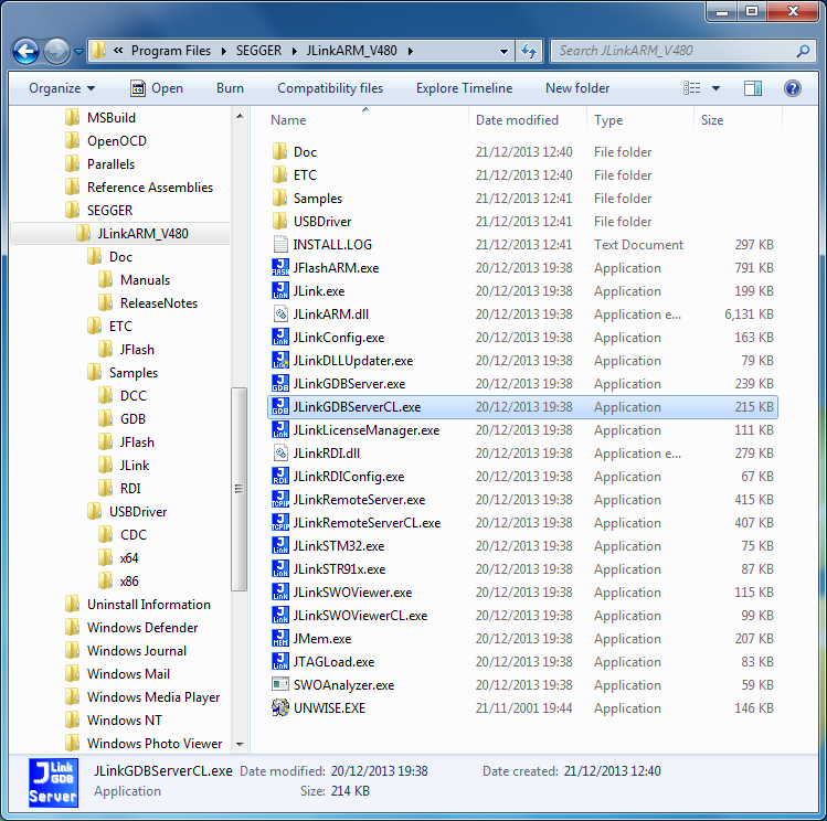
On Windows, to start the GDB server, use back-slashes in the path and the CL (command line) version:
On Ubuntu the command is simple:
In all cases, the result should be similar to the one obtained on macOS.