Usb cnc controller for key
Содержание:
- Экскурс в историю
- Command line arguments
- PlanetCNC TNG software overview and performance guidelines
- Features and specifications:
- List of supported commands
- Features and specifications:
- Контроллер из подручных материалов
- Interesting tutorials
- CNC USB Controller Mk3/4
- USING MDI IN CNC USB CONTROLLER SOFTWARE
- Controller input configuration in PlanetCNC TNG software
- PLEASE READ!!: Main differences between PlanetCNC TNG and CNC USB controller software:
- Программные инструменты
- Programs for query ″cnc usb controller full download″
- CNC USB Controller Mk3
- Starting program from g-code
Экскурс в историю
Вехи техпрогресса схематически можно обозначить так:
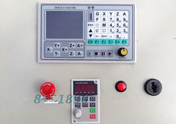
- У первого контроллера на микросхеме был условно назван «синей платой». У этого варианта есть недостатки и схема требовала доработки. Главное достоинство – есть разъем, к нему и подключали пульт управления.
- Вслед за синим, появился контроллер, называемый «красной платой». В нём уже использовались быстрые (высокочастотные) оптроны, реле шпинделя на 10А, развязка по питанию (гальваническая) и разъем, куда бы подключались драйверы четвертой оси.
- Применялось также еще одно подобное устройство с красной маркировкой, но более упрощенное. При его помощи можно было управлять небольшим станком настольного типа – из числа 3-осевых.
- Следующим в линейке техпрогресса стал контроллер с гальванической развязкой по питанию, быстрыми оптронами и особыми конденсаторами, имеющий алюминиевый корпус, который обеспечивал защиту от пыли. Вместо реле управления, которое включало бы шпиндель, в конструкции было два выхода и возможность, чтобы подключить реле или ШИМ (широтно-импульсная модуляция) управление скоростью вращения.
- Сейчас же для изготовления самодельного фрезерно-гравировального станка, имеющего ШД, есть варианты – 4-х осевой контроллер, драйвер ШД от Allegro, одноканальный драйвер для станка, имеющего большое рабочее поле.
ВАЖНО! Не стоит перегружать ШД, применяя крупную фрезу агрегата и большую скорость
Command line arguments
PlanetCNC TNG accepts commands from command line. Only one software instance can run at same time. When you run second instance it will simply pass its arguments to running instance. Running instance will process these arguments and execute command.
Here are some examples (Windows, 64bit):
1. Open command prompt.
2. Go to PlanetCNC TNG installation folder. Usually “C:Program Files (x86)PlanetCNC”.
3. Type PlanetCNC64.exe. Software will start.
4. Type PlanetCNC64.exe gcode “G01 X10G01 Y10”. You will notice that two g-code lines are now loaded.
5. Type PlanetCNC64.exe start. Machine will start and g-code will be executed.
PlanetCNC TNG software overview and performance guidelines
PlanetCNC TNG is a high performance CNC system. It is designed with flexibility in mind and it can be used for mills, routers, lathes, plasma or laser machines as well as any other machine or system where coordinated movement of servo or stepper motors is needed.
PlanetCNC TNG software works with Mk3 series of PlanetCNC motion controllers and PC running Windows 7, 8, 8.1, 10, MacOS or Linux.
Further in this post we will describe few guidelines that you can follow in order to achieve better performance of PlanetCNC TNG software and more stable communication with PlanetCNC controllers.
-
- For best performance of PlanetCNC TNG software, PC with 4 virtual processors(cores) CPU is recommended. However, PC’s with 2 virtual processors will do just fine. Various services running in the background, antivirus software and program updates can interfere with PlanetCNC TNG performance and that is why dedicated computer is recommended.
- We recommend that you connect controller to computer USB port via USB HUB device. Note that controller should be the only USB device connected on this HUB. Alternatively use USB cable with active repeater.
You see, all devices connected to the same HUB device share available bandwidth. Because data traffic is prioritized by the OS, it would not be uncommon if another device connected to same HUB would interfere with controller and therefore compromise the communication between controller and PC.You can check which devices are connected to your PC USB ports with “UsbTreeView” software. You can get it here:UsbTreeView
Images below describe bad and good type of USB connection with PC:
Example of bad USB connection with PC as seen in UsbTreeView software:
You can notice that PlanetCNC Controller is connected with PC trough various USB HUB devices(3 in total). Also, if you look closely at the USB HUB device to which PlanetCNC controller is connected, you can see that other connected devices to this USB HUB, are mass storage device and USB camera, both known as devices with huge data flow. The data flow of camera or storage device could interfere with communication of controller which as result would not perform at its best performance.
Example of good USB connection with PC as seen in UsbTreeView software:
You can see that PlanetCNC controller is connected directly to one of computers root USB ports. There are no other devices connected to root hub.
- Use double shielded USB cable. If cable longer than 1.5m is needed then it should be one with active repeater.
- If Ethernet connection is used then dedicated network card just for controller is recommended. This prevents that high network utilisation interfering with communication.
- Controller should have its own separate external power supply.
If controllers voltage is supplied only trough USB, than there is a possibility that voltage fluctuations on the USB power line could interfere with USB communication and as a result communication would drop.
For Mk3 and Mk3/4 controllers you can use 8-24VDC, 200mA power supply.IMPORTANT!!! For Mk3ECO controller power supply must be +5V VDC. - Use shielded cables for wiring of limits switches, motors…
Please note that these are not minimum requirements for controller and software to function. PlanetCNC controller can easily function on Celeron based PC’s as also controller can be connected to HUB device which serves as source for multiple other devices.
Features and specifications:
- USB (V2.x) from PC/Laptop running Windows XP, Vista, Windows 7, 8 or 8.1 (32 bit or 64bit)
- motor driver connector pin-out is compatible with 10 pin open source interface (Linistepper, PICStep)
- controller works with most step/dir stepper and servo motor drivers available on the market
- buffered IO for maximum performance
- advanced interpolation algorithms
- start, stop, pause and resume execution of program on your machine
- standard RS274/NGC G-code (EMC2 and LinuxCNC compatible)
- advanced G-codes — G40, G41, G42 (Cutter Radius Compensation) supported
- advanced G-codes — G43, G49 (Tool Length Offsets) supported
- advanced G-codes — G54, G59.3 (Coordinate System Origins) supported
- tested with SolidCAM, MasterCAM, ArtCAM, Vectric, CamBam, MeshCAM … generated G-code
- Profili 4-axes and 3-axes G-code supported
- import toolpath from DXF files
- import toolpath from PLT/HPGL files
- import toolpath from image files
- import toolpath from NC-Drill (Excellon) files
- import toolpath from Gerber (RS-274X) files
- toolpath simulation
- automatic homing procedure
- advanced toolchange procedures
- automatic tool length measuring
- export toolpath to G-code
- export toolpath to DXF
- SDK (software developers kit) is available
- works on MacOS with virtual machine emulating Windows
Mk3:
- 9 axes controller for stepper and servo motors
- USB and Ethernet connection
- 110 kHz maximum step frequency
- 25 us pulse width, 50% duty cycle at higher frequencies
- 8 digital outputs on board
- 3 PWM capable outputs with selectable frequency (10Hz to 500kHz)
- 3 outputs with support for RC servo motors
- additional outputs with add on boards (currently up to 32)
- jogging keyboard support with speed potentiometer, shift, step and spindle sync feature
- 8 limit switches with shift feature
- 8 digital inputs on board, filtered and protected
- additional inputs with add on boards (currently up to 32)
- 4 analog inputs
- MPG pendant support
- spindle encoder and index signal support for spindle synchronization
- SD card support for running g-code without computer
- control external devices with I2C and UART protocol
- homing procedure
- tool change procedure
- tool length sensor support
- sensor for capturing and measuring
- digitizing probe support
- H-bot kinematics support
- transformation matrix
- soft limits
- slave axes
- backlash compensation
- integrated web server for monitoring state and sending commands
- API
Mk2:
- 9 axes controller for stepper and servo motors
- USB connection
- 100 kHz maximum step frequency
- 12 us minimum pulse width, 50% duty cycle at higher frequencies
- 7 digital outputs on board
- jogging keyboard support
- 8 limit switches with shift feature
- 5 inputs
- MPG pendant support
- spindle encoder and index signal support for spindle synchronization
- SD card support for running g-code without computer
- control external devices with I2C and UART protocol
- homing procedure
- tool change procedure
- tool length sensor support
- sensor for capturing and measuring
- digitizing probe support
- transformation matrix
- soft limits
- slave axes
- backlash compensation
- API
Mk2/4:
- 4 axes controller for stepper and servo motors
- USB connection
- 100 kHz maximum step frequency
- 12 us minimum pulse width, 50% duty cycle at higher frequencies
- 3 digital outputs on board
- jogging keyboard support
- 4 limit switches
- 4 inputs
- spindle index signal support for spindle synchronization
- homing procedure
- tool change procedure
- tool length sensor support
- sensor for capturing and measuring
- digitizing probe support
- transformation matrix
- soft limits
- slave axes
- backlash compensation
- API
- screw terminal connectors for connecting motor drivers, inputs and outputs
Mk1:
- 4 axes controller for stepper motors
- 25 kHz maximum step frequency
- 3 digital outputs (flood, mist, spindle)
- jog inputs for all axes
- limit inputs for all axes
| Turning using tool change (lathe) | Turning with threading using tool change (lathe) |
| Threading (lathe) | Threading by hand (lathe — spindle synchronization demo) |
| Testing 4th rotary axis | Moai statue with 4th rotary axis |
| Digitizing 3D model with probe | Measuring surface and generating STL file |
| «Warp» — measuring and cutting warped toolpath | Making PCB for CNC USB Controller |
| Cutting «NeoCrossbones» | Using working offset and tool sensor |
| Automatic Tool Changer (ATC) | 1st run of my new machine |
List of supported commands
Both options described above use same commands. Here is a list and brief explanation.
show Shows main window
hide Hides main window
exit Exits program
estop Toggles EStop
start Performs Start
stop Performs Stop
pause Performs Pause
isestop Returns 1 if EStop is active, 0 otherwise
ispause Returns 1 if Pause is active, 0 otherwise
open "filename" Opens GCode from file
gcode "program" Opens GCode from string
close Closes opened GCode
mdi "command" Executes MDI command
param name=value Sets parameter value
param name Returns parameter value
posabs Returns absolute position for all axes
posabsx Returns absolute position for X axis
posabsy Returns absolute position for Y axis
posabsz Returns absolute position for Z axis
posabsa Returns absolute position for A axis
posabsb Returns absolute position for B axis
posabsc Returns absolute position for C axis
posabsu Returns absolute position for U axis
posabsv Returns absolute position for V axis
posabsw Returns absolute position for W axis
pos Returns position for all axes
posx Returns position for X axis
posy Returns position for Y axis
posz Returns position for Z axis
posa Returns position for A axis
posb Returns position for B axis
posc Returns position for C axis
posu Returns position for U axis
posv Returns position for V axis
posw Returns position for W axis
speed Returns current speed
accel Returns current acceleration
spindle Returns current spindle RPM
input Returns value of INPUT
input1 Returns value of INPUT 1 pin
input2 Returns value of INPUT 2 pin
input3 Returns value of INPUT 3 pin
input4 Returns value of INPUT 4 pin
input5 Returns value of INPUT 5 pin
input6 Returns value of INPUT 6 pin
input7 Returns value of INPUT 7 pin
input8 Returns value of INPUT 8 pin
jog Returns value of JOG
jog1 Returns value of JOG 1 pin
jog2 Returns value of JOG 2 pin
jog3 Returns value of JOG 3 pin
jog4 Returns value of JOG 4 pin
jog5 Returns value of JOG 5 pin
jog6 Returns value of JOG 6 pin
jog7 Returns value of JOG 7 pin
jog8 Returns value of JOG 8 pin
joga1 Returns value of JOG A1 pin
joga2 Returns value of JOG A2 pin
jogs Returns value of JOG S pin
jogpot Returns value of JOG POT
limit Returns value of LIMIT
limit1 Returns value of LIMIT 1 pin
limit2 Returns value of LIMIT 2 pin
limit3 Returns value of LIMIT 3 pin
limit4 Returns value of LIMIT 4 pin
limit5 Returns value of LIMIT 5 pin
limit6 Returns value of LIMIT 6 pin
limit7 Returns value of LIMIT 7 pin
limit8 Returns value of LIMIT 8 pin
limit9 Returns value of LIMIT 9 pin
output Returns value of OUTPUT
output1 Returns value of OUTPUT 1 pin
output2 Returns value of OUTPUT 2 pin
output3 Returns value of OUTPUT 3 pin
output4 Returns value of OUTPUT 4 pin
output5 Returns value of OUTPUT 5 pin
output6 Returns value of OUTPUT 6 pin
output7 Returns value of OUTPUT 7 pin
output8 Returns value of OUTPUT 8 pin
aux1 Returns value of AUX 1 pin
aux2 Returns value of AUX 2 pin
aux3 Returns value of AUX 3 pin
aux4 Returns value of AUX 4 pin
buffer Returns amount of free buffer
bufferpercent Returns percent of buffer utilization
linecount Returns number of lines in GCode program
line Returns line number currently executing
Features and specifications:
Torch height sensor device:
• Plasma arc voltage measurement up to 350 V
• Additional input for divided plasma voltage (1:50) up to 10 V
• Plasma voltage present signalization
• Full optical output isolation; transmitter and receiver connected over an optical fiber
cable
• Main AC power supply (110 VAC-230 VAC/50-60 Hz)
Torch height controller:
• Output signals: Arc Ok, Up and Down (normally-open solid-state relay outputs)
• Programmable reference and hysteresis voltage, delay time and anti-dive limit voltage
• Current plasma voltage presentation on LED display
• LED signalization of arc present, up and down signals
• Full optical input isolation; transmitter and receiver connected over an optical cable
• Test mode operation
• Wide power supply voltage range (6 – 36 V)
Torch height controller terminal description:
Torch height sensor terminal description:
Контроллер из подручных материалов
Большинство умельцев предпочитают управление через LPT порт для большинства программ управления любительского уровня. Вместо применения комплекта спецмикросхем для этой цели, кое-кто строит контроллер из подручных материалов – полевых транзисторов из сгоревших материнских плат (при напряжении свыше 30 вольт и током больше 2 ампер).
А поскольку создавался станок для нарезания пенопласта, в качестве ограничителя тока изобретатель использовал автомобильные лампы накаливания, а ШД снимали со старых принтеров или сканеров. Такой контроллер устанавливали без изменений в схеме.
Чтобы сделать простейший станок ЧПУ своими руками, разбирая сканер, помимо ШД, извлекается и микросхема ULN2003, и два стальные прутки, они пойдут на тестовый портал. К тому же понадобятся:
- Коробка из картона (из нее смонтируют корпус устройства). Возможен вариант с текстолитом или фанерным листом, но картон резать легче; куски древесины;
- инструменты – в виде кусачек, ножниц, отверток; клеевой пистолет и паяльные принадлежности;
- вариант платы, которая подходит на самодельный ЧПУ станок;
- разъем для LPT порта;
- гнездо в форме цилиндра для обустройства блока питания;
- элементы соединения – стержни с резьбой, гайки, шайбы и шурупы;
- программа для TurboCNC.
Сборка самодельного устройства
Приступив к работе над самодельным контроллером для чпу, первый шаг – аккуратно припаять микросхему на макетную плату с двумя шинами электропитания. Дальше последует соединение вывода ULN2003 и коннектора LPT. Далее оставшиеся выводы подключаем по схеме. Нулевой вывод (25-ый параллельного порта) соединяется с отрицательным на шине питания платы.
Затем ШД соединяют с устройством управления, а гнездо для электропитания – с соответствующей шиной. Для надёжности соединений проводов выполняют их фиксацию термоклеем.
Не составит труда подключение Turbo CNC. Программа эффективна с MS-DOS, совместима и с Windows, но в этом случае возможны некоторые ошибки и сбои.
Настроив программу на работу с контроллером, можно изготовить тестовую ось. Последовательность действий по подключению станков такова:
- В отверстия, просверленные на одном уровне в трех деревянных брусках, вставляют прутки из стали и закрепляют шурупами небольшого размера.
- ШД соединяют со вторым бруском, надевая его на свободные концы прутов и прикручивают, применяя шурупы.
- Через третье отверстие продевается ходовой винт и ставится гайка. Винт, вставленный в отверстие второго бруска, завинчивают до упора, чтобы он, пройдя через эти отверстия, вышел на вал двигателя.
- Далее предстоит соединение стержня с валом двигателя отрезком шланга из резины и проволочным зажимом.
- Для крепления ходовой гайки нужны дополнительные винты.
- Сделанная подставка также крепится к второму бруску при помощи шурупов. Горизонтальный уровень регулируется дополнительными винтами и гайками.
- Обычно вместе с контроллерами подключаются и двигатели и тестируются на предмет правильного соединения. Далее следует проверка масштабирования ЧПУ, прогонка тестовой программы.
- Остается сделать корпус устройства и это будет завершающим этапом работы тех, кто созидает самодельные станки.
Программируя работу 3-осевого станка, в настройках по первым двум осям – без перемен. А вот при программировании первых 4-х фаз третьей – вводятся изменения.
Внимание! Используя упрощенную схему контроллера ATMega32 (Приложение 1), в отдельных случаях можно столкнуться с некорректной обработкой оси Z – режим полушага. А вот в полной версии его платы (Приложение 2), токи осей регулируются внешним аппаратным ШИМом
Interesting tutorials
How to use Xbox One controller on Mac OS X
… available for download on the … to Micro B USB 2.0 cable). If … of your controller‘s buttons, …
How to run a portable version of Windows from your USB device
… a portable Windows USB drive, I … suggest using a USB 3.0 flash … need to download the …
How to remove the write protection from a USB drive
… write-protected. USB drives can … protection from a USB drive.
1. … for a USB drive. Here …
How to create bootable USB flash and pen drive for Windows
… Making bootable USB flash or … find and download these … Creating bootable USB drive from …
How to transfer files from a Mac desktop to an external hard drive
… desktop to a USB flash drive … or USB stick, the … to an USB drive or …
How to transfer all files to a new computer
… transferring via USB cable, … .
Step 1
Download and install … via 3.0 USB ports.
Conclusion …
How to control your Android phone from a PC
… do:
Step 1
Download the ADB … USB cable. Make sure the USB … offers you full control over …
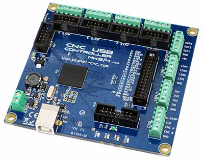
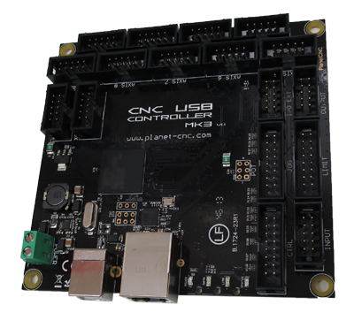
CNC USB Controller Mk3/4
 |
|
USING MDI IN CNC USB CONTROLLER SOFTWARE
MDI stands for ‘Manual Data Input’. MDI window is located in the bottom right corner of CNCUSB controller software main window:
By entering MDI shortcuts or g-code commands in this window, user can quickly access desired feature, executes g-code command or performs machine specific task.
MDI shortcuts:
You probably already noticed that almost every feature in almost any menu has a number written on the right side of its name starting with symbol “/”. This is its unique MDI shortcut.
If you don’t have any idea about MDI and of its use, it would the best to start with typing “/101” in MDI window and see what happens. Now enter “/151” into MDI window.
First MDI shortcut executed ‘Open’ dialog and second one opened ‘Settings’ menu.
You can browse trough files or change settings configuration with less mouse clicks than if you would click your way trough the menus.
From operators point of view this reflects as more fluent and prompt way of working with machine.
Using arrow keys “Up” and “Down”, user can navigate trough history of previously used MDI shortcuts or MDI g-codes.
One of the best advantages of MDI is gained accessibility of many features provided by CNC USB controller software.
Pretty common step when preparing your workpiece for cutting is setting offsets or capturing points. All these features can be accessed or set using MDI.
Setting XY offset:
If you would want to set XY offset at current machines position, you could click: Machine/Offset/Current XY.
You could do the same thing just by entering “/45251” in MDI window:
Capturing Camera Point:
MDI is especially useful for certain repetitive procedures, like capturing points with camera.
If you want to capture point using camera, you could click Machine/Capture & Measure Points /Capture/Capture Camera Point. You would have to do that for every point you would want to capture.
You could do the same just by entering “ /48102” in MDI window:
If you run a feature directly from menu or a toolbar, then from that point on, this feature will be available in MDI history, and you can find and select it with arrow keys.
MDI g-codes:
You can set and perform machine moves, control outputs or change tools directly from MDI window.
Examples:
Machine traverse and feed moves:
Typing moves machine to X=10 position at traverse rate.
Typing moves machine to Y= -20 position at traverse rate.
Typing moves machine to Y=10 position at feed rate = 100.
Output control:
Using M3, M5, M7, M8 and M9 g-codes you can control outputs:
Typing will turn Spindle ON and will turn Spindle OFF.
Typing will turn Mist ON and will turn Mist OFF.
Tool change:
You can change or select tool directly from MDI window:
Typing changes tool.
Typing selects desired tool.
Configuring machine settings:
Some machine settings are very easy to be configured with the use of MDI. One of them is whether machine operates in ‘Absolute Distance Mode’ or in ‘Incremental Distance Mode’.
G90 – absolute distance mode:
To move machine in ‘Absolute Distance Mode’ on location of you can enter this command:
G91- Incremental distance mode:
To move machine in ‘Incremental Distance Mode’ for distance of , you enter this command:
G53 – absolute machine coordinate system:
You can set your machine moves in absolute machine coordinate system.
To move your machine in absolute machine coordinate system on location of you can enter this command:
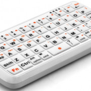
Wireless keypad or Shuttle PRO are very practical to work with MDI and for operating with CNC USB controller in general.
MDI offers many possibilities for operator and it is best that each user explores the possibilities of the MDI for itself.
Controller input configuration in PlanetCNC TNG software
User can configure controller inputs for THC under File/Settings/THC.
Axis:
User selects machine axis from drop down menu. Selected axis will be height compensated.
Dec Pin:
Dec input pin number, located at INPUT header of controller. Select input pin number from drop down menu.
When this input pin is active, machine will move/compensate in negative direction.
Down signal from torch height controller is connected to this input.
Inc Pin:
Inc input pin number, located at INPUT header of controller. Select input pin number from drop down menu.
When this input pin is active, machine will move/compensate in positive direction.
Up signal from torch height controller is connected to this input.
OK Pin:
OK input pin number, located at INPUT header of controller. Select input pin number from drop down menu.
If set, software waits until this input is active and only then begins with program execution.
Arc OK signal from torch height controller is connected to this input.
Range Min/Max:
Low and high limit compensation travel.
Speed:
Speed of compensation moves. Units are mm/s or inch/s.
When torch height controller will activate its output, corresponding digital input of controller should activate.
You can observe status of controller inputs via IO tab of PlanetCNC TNG state panel.
PLEASE READ!!: Main differences between PlanetCNC TNG and CNC USB controller software:
1.) You can use two motion control software’s from PlanetCNC with your MK3 series controller:
PlanetCNC TNG or CNC USB controller.
2.) Controller’s firmware needs to be updated with the version you tend to use: PlanetCNC TNG or CNC USB controller
3.) You cannot use controller which firmware is updated with PlanetCNC TNG software with CNC USB sw and
you cannot use controller which firmware is updated with CNC USB controller software with PlanetCNC TNG.
4.) Each version of SW accepts its unique license key to activate controller.
Form of CNC USB license key (example only):
License for controller with activation code “LUxx-xxxx-xxxx-MJRX” and serial number “572”
u64/st0ByELl2ak5Kcqlsey0J/4g29c6fJ7mEIctwmZ/kffdz+EUJ2zGWpLeU05iUf+aQhO/BaMbSr07yTw==
Form of PlanetCNC TNG license key (example only):
<key code=”CUBRQ-3CNR9-PCX6K-3DV7X-SE3E5-ZHBS”>
Q9NK7DFMQGQ16ADYF9NSFYV8B1B519WXHEJ6D72EZVAYMH0QVDK86KDGH4MC797B971BVJP2N171PZDM9QBW9ZRJ9RHQS9NQS4QW
</key>
You cannot use license key for CNC USB with PlanetCNC TNG and vice versa
5.) Once you purchase license for your controller you are entitled to both controller licenses. You do not need to purchase controller license for each software version. However, license for controller needs to be purchased.
Программные инструменты
Объединение программных инструментов с целью обустройства конструкторской части изготовления осуществляется по таким ключевым ориентациям:
- интегрирование конструкторских Систем Автоматизированного Проектирования;
- объединение технологических САПР;
- составление САПР с системами PDM.
Интеграция концепций персональных разработок
Это более трудный процесс, ведь данные исследования нередко имеют провал в связи с устаревшей управляющей структурой наряду с иными негативными моментами. Эти уникальные профессиональные структуры имеют много методов приспособления к решению интеграционных проблем, тем не менее, их вероятность приобщения к интегрированию в виде функциональных возможностей, в основном значительно уменьшается.
Высокий уровень требований к характеристикам деталей имеют огромный потенциал со стороны развития услуг в процессе регуляции уровня качества. Трудоемкость ключевых действий над сложно обрабатываемыми элементами может достигнуть 30% трудоемкости при их изготовлении.
Данная информационная модель свидетельствует о делении интеграции применяемого программного обеспечения на две направленности:
- Первая – процесс цикличной интеграции: «конструирование продукта — производственное приготовление — процесс производства».
- Вторая – интеграция программных средств, которые применяют в этом обороте, с замкнутой системой информационного обеспечения организации, построением управленческих данных о продуктах и обеспечением организации.
Интеграция жизненного цикла с техническими процессами размерной, а также механической обработки осуществляется благодаря программным возможностям: концепции автоматизированной проектировки и концепции рассортированного управления станками с численным программным управлением.
Эксплуатация данной информативной формы детали в объединенном построении CAD/CAE/CAM делает возможным начало разработки технических процессов, которые являются допустимыми благодаря управляющим инженерам-технологам. В таком случае снабжение руководящих планов с целью снабжения с числовым программным управлением возможно без ожидания конечного завершения периода инженерного конструирования. Пока проектировщики завершают начатые работы с компоновкой, технологи начинают работать над созданием технических процессов производства образовывающих ее деталей на станке.
Если необходимо поправить допустимые оплошности проектировщиков, они могут отрабатывать проектировочные документы на технологичность, что предусмотрено отраслевой предписанной документацией. На данном этапе сокращается время и средства, которые затрачивают на конструкторские действия и обработку недавно появившихся деталей, что в свою очередь позволит оптимальное использование коллективного опыта производителей.
Programs for query ″cnc usb controller full download″
Grbl Controller
Download
4.2 on 645 votes
Grbl Controller is designed to send GCode to CNC machines, such as 3D milling machines.
Grbl Controller is designed … GCode to CNC machines, such … to whatever controller they are …
ECam
Download
4.3 on 23 votes
ECam is a programming system for CNC lathes and machining centers.
… system for CNC lathes and … to be a full CAD system …
CNC-SIMULATOR
Download
3.5 on 232 votes
The idea of the new CncSimulator is to provide the machining industry with a contemporary competent Fanuc-like CNC ISO simulator.
… Fanuc-like CNC ISO simulator … simulate in full 3D with … and more. CNC Machine profiles …
Mach3
Download
3.6 on 97 votes
The Mach series of software was originally developed for the home hobbyist, but has quickly turned into one of the most …
… most versatile control packages for … featured, 6-axis CNC controller , allows direct …
3DView (C:WinNC32 fanuc)
Download
2.3 on 3 votes
Win3D-View is a 3D simulation for turning and milling and is available as an option in addition to the WinNC Control.
… simulations of CNC controls are designed … understood and controlled from the …
123D Design
Download
4.1 on 82 votes
123D Design is a free, powerful, yet simple 3D creation and editing tool which supports many new 3D printers.
… manufactured with CNC, laser cutters …
MOST 2D
Download
3.2 on 22 votes
MOST 2D is a nesting software for sheet metal cutting and heavy fabrication.
… number of cnc gas, plasma …
Scm Group
Xilog Plus
Download
3 on 32 votes
The software Xilog Plus from the SCM Group is used to manage the CNC-machining centres with numerical control.
… CNC-machining centres with numerical control … machine control panel. … machine control panel …
CIMCO Edit
Download
3.8 on 183 votes
CIMCO Edit is a powerful editor designed for professional CNC programmers.
… for professional CNC programmers. It … of modern CNC program editing …
Swansoft CNC Simulator
Download
4 on 102 votes
Swansoft CNC Simulator is real-time 3D CNC machine system simulation and advanced G-code verification application.
Swansoft CNC Simulator is … -time 3D CNC machine system … all the CNC machine operations …
CNC USB Controller Mk3
 |
|
Starting program from g-code
You can also start your own program from gcode. Optionally you can wait for program to finish before g-code continues or you can pass parameters.
Start myprogram.exe:(exec,myprogram.exe)
Start myprogram.exe and send current X and Y coordinates:(exec,myprogram.exe #<_x> #<_y>)
Start myprogram.exe, send current X and Y coordinates and wait for program to finish:(execwait,myprogram.exe #<_x> #<_y>)
Make sure that myprogram.exe is added to whitelist in settings otherwise TNG will refuse to execute it.
Hint: This external program can use named pipes to set some g-code parameters. TNG will use these parameters when g-code execution will continue.