Даташит stps2045ct pdf ( datasheet )
STPS2045CT Datasheet Download — ST Microelectronics
| Номер произв | STPS2045CT | |||
| Описание | POWER SCHOTTKY RECTIFIER | |||
| Производители | ST Microelectronics | |||
| логотип | ||||
1Page
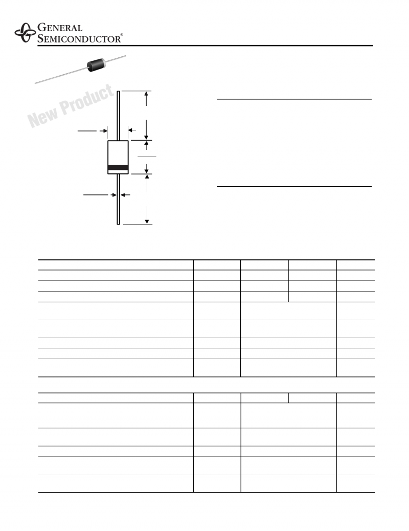
STPS2045CT/CF/CG/CFP POWER SCHOTTKY RECTIFIER IF(AV) VRRM Tj (max) VF (max) 2 x 10 A s VERY SMALL CONDUCTION LOSSES s NEGLIGIBLE SWITCHING LOSSES s EXTREMELY FAST SWITCHING s INSULATED PACKAGE: ISOWATT220AB, TO-220FPAB TO-220FPAB or D2PAK, this device is especially intended for use in low voltage, high frequency D2PAK STPS2045CG ABSOLUTE RATINGS (limiting values, per diode) Symbol VRRM IF(RMS) IF(AV) Repetitive peak reverse voltage Average forward TO-220AB / D2PAK current δ = 0.5 ISOWATT220AB IFSM IRRM Surge non repetitive forward current tp = 2 µs square F = 1kHz IRSM Tstg -65 to +175 °C Tj Maximum operating junction temperature * 10000 V/µs * : dPtot < 1 thermal runaway condition for a diode on its own heatsink dTj Rth( j − a) August 2002 — Ed: 3E
STPS2045CT/CF/CG/CFP Rth (j-c) Junction to case Parameter TO-220AB / D2PAK Rth (c) ISOWATT220AB TO-220AB / D2PAK ISOWATT220AB ∆ Tj (diode 1) = P (diode1) x Rth(j-c) (per diode) + P (diode 2) x Rth(c) STATIC ELECTRICAL CHARACTERISTICS (Per diode) Value Unit Per diode 2.2 °C/W Total IR * Reverse leakage current VF * Forward voltage drop Tests Conditions VR = VRRM Tj = 125°C Tj = 125°C IF = 10 A Tj = 25°C IF = 20 A Tj = 125°C IF = 20 A Min. Typ. Max. µA mA Pulse test : * tp = 380 µs, δ < 2% To evaluate the conduction losses use the following equation : P = 0.42 x IF(AV) + 0.015 IF2(RMS) 2/7
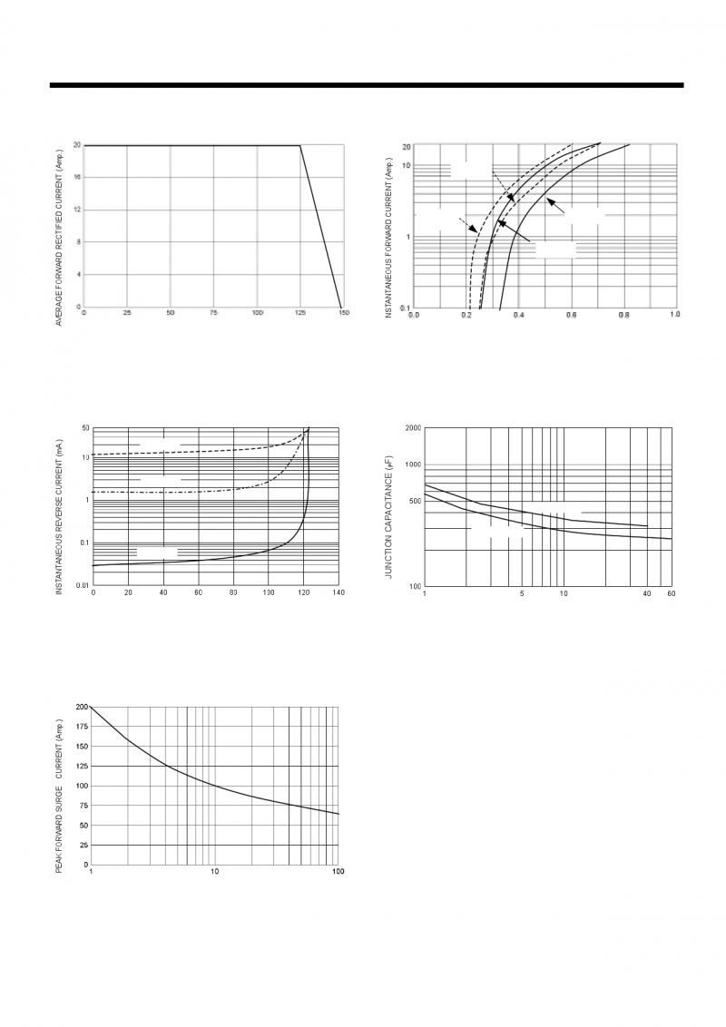
Fig. 1: Average forward power dissipation versus average forward current (per diode). Fig. 2: Average current versus ambient temperature (δ=0.5, per diode). PF(av)(W) δ = 0.1 δ = 0.2 7 δ = 0.05 6 1 IF(av) (A) 01234567 δ = 0.5 δ=1 T δ=tp/T tp δ=tp/T 0 25 Fig. 3-1: Non repetitive surge peak forward current versus overload duration (maximum values, per diode) (TO-220AB and D2PAK). Fig. 3-2: Non repetitive surge peak forward current versus overload duration (maximum values, per IM 20 1E-3 δ=0.5 t(s) 1E-2 IM 20 δ=0.5 t(s) 1E-3 Fig. 4-1: Relative variation of thermal transient impedance junction to case versus pulse duration (TO-220AB and D2PAK). Fig. 4-2: Relative variation of thermal transient impedance junction to case versus pulse duration 0.6 δ = 0.5 0.4 0.2 δ = 0.2 δ = 0.1 Single pulse δ=tp/T 1E-1 0.6 δ = 0.5 0.4 0.2 δ = 0.2 δ = 0.1 Single pulse δ=tp/T 1E+0 |
||||
| Всего страниц | 8 Pages | |||
| Скачать PDF |


